


1-20
Hardware Specifications and Configurations
Application key
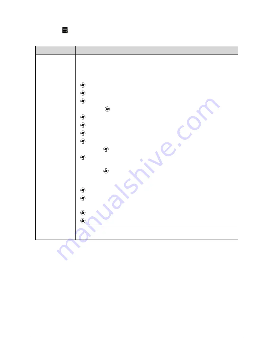
Table 1-8. Windows Keys
Key
Description
Windows Logo
key
Pressed alone, this key has the same effect as clicking on the Windows Start
button; it launches the Start menu. It can also be used with other keys to
provide a variety of functions.
Functions supported by Windows XP, Windows Vista, and Windows 7:
<
>: Open or close the Start menu
<
> + <R>: Open the Run dialog box
<
> + <M>: Minimizes all windows
<SHIFT> + <
> + M: Undo minimize all windows
<
> + <F1>: Show the help window
<
> + <E>: Open Windows Explorer
<
> + <F>: Search for a file or folder
<
> + <D>: Show the desktop
<CTRL> + <
> + <F>: Search for computers (search in network)
<
> + <L>: Lock computer (if connected to a network domain), or switch
users (if not connected to a network domain)
<CTRL> + <
> + <TAB>: Moves focus from Start menu, to the Quick
Launch toolbar, to the system tray (use RIGHT ARROW or LEFT ARROW to
move focus to items on the Quick Launch toolbar and the system tray)
<
> + <TAB>: Cycle through programs on the taskbar
<
> + <BREAK>: Display the System Properties dialog box
Functions supported by Windows XP:
<
> + <BREAK>: Show the System Properties dialog box
<
> + <U>: Open Ease of Access Center
Application key
This key has the same effect as clicking the right mouse button; opening the
application's context menu.
Содержание Aspire 7739
Страница 19: ...Hardware Specifications and Configurations 1 23 System Block Diagram 0 Figure 1 9 System Block Diagram ...
Страница 36: ...1 40 Hardware Specifications and Configurations ...
Страница 59: ...System Utilities 2 25 5 Execute RU bat to read SMBIOS Type 1 UUID Figure 2 27 Figure 2 28 Read UUID ...
Страница 60: ...2 26 System Utilities 6 Execute WU bat to write SMBIOS Type 1 UUID Figure 2 28 Figure 2 29 Write UUID ...
Страница 64: ...2 30 System Utilities ...
Страница 71: ...3 11 Figure 3 7 HDD Module Figure 3 8 HDD Module 3 Remove HDD follow the arrowhead ...
Страница 72: ...3 12 Figure 3 9 HDD Module Figure 3 10 HDD Module ...
Страница 74: ...3 14 Figure 3 13 WLAN Module ...
Страница 77: ...3 17 Figure 3 19 Memory Module Figure 3 20 Memory Module Figure 3 21 Memory Module ...
Страница 78: ...3 18 Removing Main screws on bottom case 0 1 Remove 26 M2 5 6 screws on bottom case Figure 3 22 MAIN SCREWS ...
Страница 82: ...3 22 ...
Страница 86: ...3 26 Figure 3 35 TOP Case Figure 3 36 TOP Case ...
Страница 89: ...3 29 Figure 3 42 I O BD Figure 3 43 I O BD ...
Страница 91: ...3 31 Figure 3 46 Mother board Figure 3 47 Mother board 3 Take out the RTC battery ...
Страница 92: ...3 32 Figure 3 48 RTC BATTERY Figure 3 49 RTC BATTERY ...
Страница 94: ...3 34 Figure 3 51 Thermal Figure 3 52 Thermal Figure 3 53 Thermal ...
Страница 100: ...3 40 Figure 3 64 LCD Module Figure 3 65 LCD Module 3 Disconnect LVDS Cable Figure 3 66 LCD Module ...
Страница 101: ...3 41 4 Disconnect the Camera Cable and take the camera module away Figure 3 67 LCD Module Figure 3 68 LCD Module ...
Страница 103: ...3 43 Figure 3 71 LCD Panel Figure 3 72 LCD Panel 4 Put camera and MIC in the right place ...
Страница 104: ...3 44 Figure 3 73 LCD Panel Figure 3 74 LCD Panel ...
Страница 107: ...3 47 Figure 3 79 Hinge ...
Страница 109: ...3 49 Figure 3 82 Thermal Module Figure 3 83 Thermal Module ...
Страница 111: ...3 51 Figure 3 86 Main board Figure 3 87 Main board ...
Страница 113: ...3 53 Figure 3 90 ODD BD Figure 3 91 ODD BD 2 Connect IO BD and ODD B D FFC CONN ...
Страница 114: ...3 54 Figure 3 92 IO BD Figure 3 93 ODD BD ...
Страница 117: ...3 57 Figure 3 98 Top case Figure 3 99 Top case ...
Страница 119: ...3 59 Figure 3 102 Top case Figure 3 103 Top case Figure 3 104 Top case ...
Страница 124: ...3 64 Figure 3 113 ...
Страница 126: ...3 66 Figure 3 116 2 Secure 26 M2 5 6L screws on bottom case Figure 3 117 3 Install main door secure 2 screws M2 6L ...
Страница 127: ...3 67 Figure 3 118 HDD Module Figure 3 119 HDD Module Replacing Battery Module 0 1 Install the battery on bottom case ...
Страница 128: ...3 68 Figure 3 120 Battery ...
Страница 154: ...4 28 Troubleshooting ...
Страница 186: ...6 28 FRU Field Replaceable Unit List ...
Страница 200: ...7 16 Model Definition and Configuration ...


