


Chapter 3
43
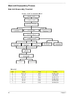
External Module Disassembly Process
External Modules Disassembly Flowchart
The flowchart below gives you a graphic representation on the entire disassembly sequence and instructs you
on the components that need to be removed during servicing. For example, if you want to remove the main
board, you must first remove the keyboard, then disassemble the inside assembly frame in that order.
Screw List
Item
Screw
Color
Part No.
B
M2.5 x L7
Black
86.00E72.637
C
M2 x L3
Silver
86.00F80.723
D
M3 x L4
Silver
86.9A554.4R0
F
M2 x L4
Silver
86.9A552.4R0
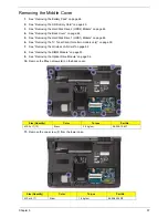
EXTERNAL MODULE DISASSEMBLY
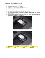
WLAN
BOARD
TURN OFF POWER
AND PERIPHERALS
UNPLUG POWER
CABLES
Fx1
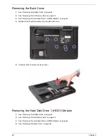
BACK
COVER
Captive Screwx6
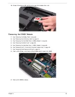
DIMM
MODULES
REMOVE BATTERY
PACK
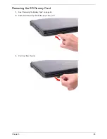
SD DUMMY CARD
Cx1
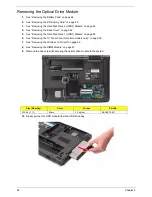
ODD
MODULE
OPTICAL DISK
DRIVE
OPTICAL
LOCKER
BRACKET
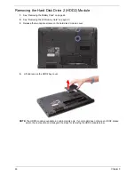
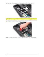
HDD 2
COVER
Captive Screwx2
Dx2
HDD 2
MODULE
HARD DISK
BRACKET
HARD DISK
DRIVE
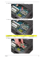
Dx2
HDD 1
MODULE
HARD DISK
BRACKET
HARD DISK
DRIVE
Cx1
Bx1
TV TUNER
BOARD
Fx1
Содержание Aspire 7235 Series
Страница 6: ...VI ...
Страница 12: ...4 Chapter 1 System Block Diagram For Aspire 7738 7738G Series and 7735 7735G 7735Z 7735ZG Series ...
Страница 13: ...Chapter 1 5 For Aspire 7535 7535G 7235 Series ...
Страница 191: ...Appendix A 183 Model Definition and Configuration Appendix A ...
Страница 212: ...Appendix A 204 ...
Страница 216: ...208 Appendix B ...
Страница 218: ...210 Appendix C ...


