


74
Chapter 3
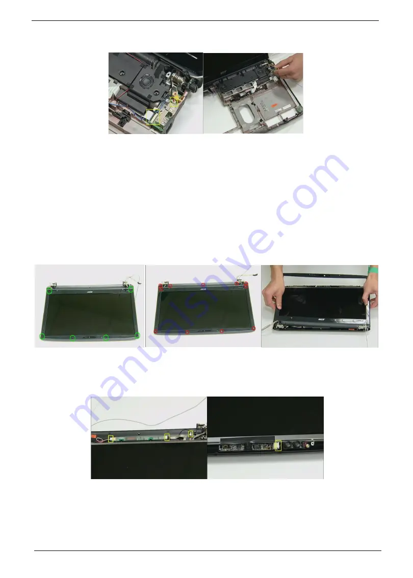
19.
Disconnect LED/B cable and USB/B FFC.
20.
Remove the USB board from BTCB..
21.
Loose two Modem card screws.
22.
Disconnect Modem card cable.
23.
Remove Modem card from the M/B.
Disassembly LCM module
1.
Remove six LCM bezel mylar.
2.
Loose 11 LCM bezel screws.
3.
Remove LCM bezel.
4.
Disconnect Inverter cable and Back LED board cable.
5.
Disconnect CCD cable..
6.
Loose four LCD scrws from the hinge.
7.
Remove the LCD panel.
Содержание Aspire 6920
Страница 6: ...VI ...
Страница 10: ...4 Chapter 1 System Block Diagram ...
Страница 11: ...Chapter 1 5 Board Layout ...
Страница 12: ...6 Chapter 1 ...
Страница 14: ...8 Chapter 1 Closed Front View ...
Страница 15: ...Chapter 1 9 Left View ...
Страница 16: ...10 Chapter 1 Right View ...
Страница 17: ...Chapter 1 11 ...
Страница 18: ...12 Chapter 1 Base view ...
Страница 30: ...24 Chapter 1 ...
Страница 62: ...62 Chapter 2 Then the HDD password will be unlocked and will auto into Windows after reboot ...
Страница 66: ...64 Chapter 3 ...
Страница 67: ...Chapter 3 65 Removing the Battery Pack 1 Release the battery 2 Slide the battery latch then remove the battery ...
Страница 77: ...Chapter 3 75 8 Remove the Inverter board 9 Loose four LCD hinge screws then remove two hinges from LCD panel ...
Страница 97: ...Chapter 5 97 Jumper and Connector Locations Chapter 5 ...
Страница 98: ...98 Chapter 5 Bottom View ...
Страница 99: ...Chapter 5 99 ...
Страница 100: ...100 Chapter 5 ...
Страница 102: ...100 Chapter 6 Aspire6920 Exploded Diagram ...
Страница 103: ...Chapter 6 101 ...
Страница 104: ...102 Chapter 6 ...
Страница 105: ...Chapter 6 103 ...


