


Chapter 1
7
NOTE:
1
The front panel indicators are visible even when the computer cover is closed.
Closed Front View
Left View
7
Power
1
Indicates the computer’s power status.
Battery
1
Indicates the computer’s battery status.
1.
Charging: The light shows amber when the
battery is charging.
2.
Fully charged: The light shows blue when in
AC mode.
8
Click buttons (left
and right)
The left and right buttons function like the left
and right mouse buttons.
9
Palmrest
Comfortable support area for your hands when
you use the computer.
10
Speakers
Left and right speakers deliver stereo audio
output.
11
Microphone
Internal microphone for recording sound.
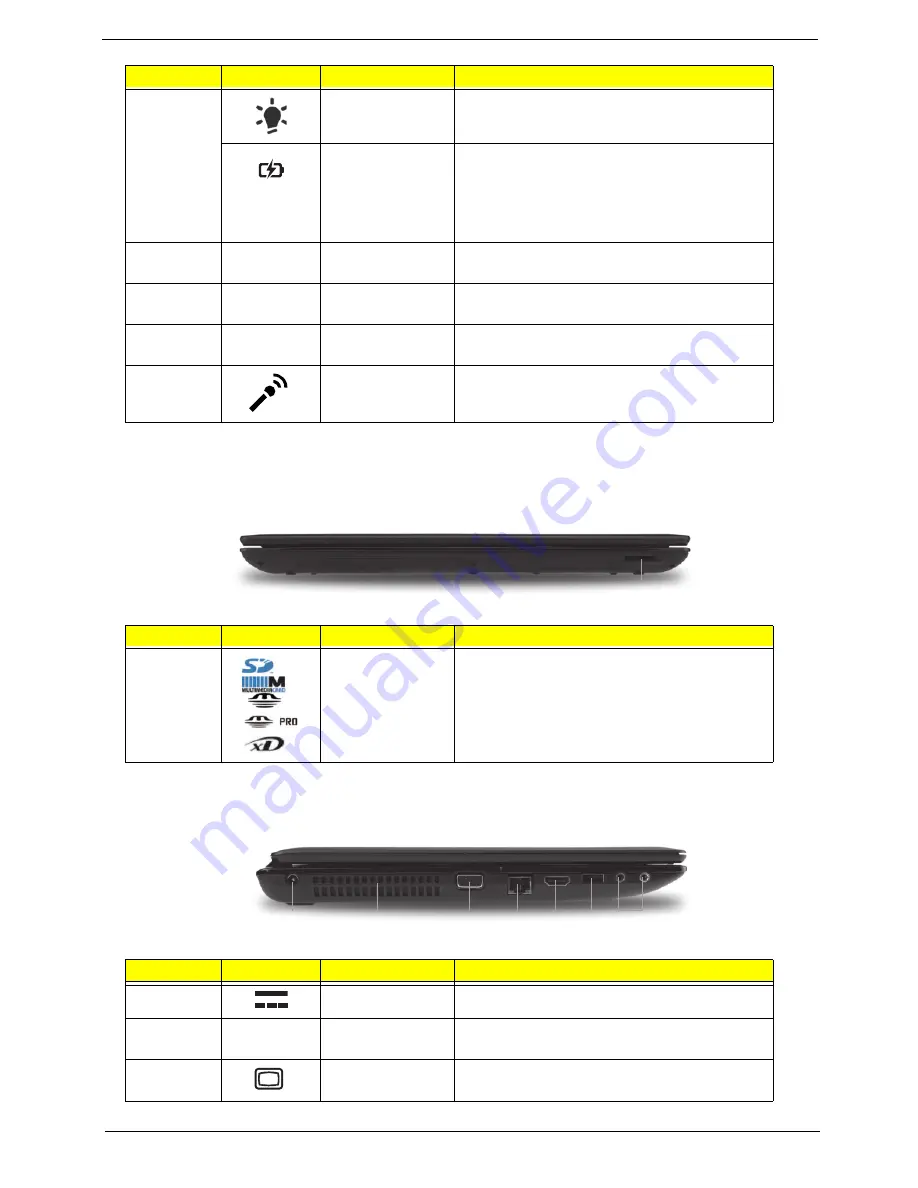
No.
Icon
Item
Description
1
Multi-in-1 card
reader
Accepts Secure Digital (SD), MultiMediaCard
(MMC), Memory Stick (MS), Memory Stick
PRO (MS PRO), xDPicture Card (xD).
NOTE:
Push to remove/install the card.
Only one card can operate at any
given time.
No.
Icon
Item
Description
1
DC-in jack
Connects to an AC adapter
2
Ventilation slots
Enable the computer to stay cool, even after
prolonged use.
3
External display
(VGA) port
Connects to a display device
(e.g. external monitor, LCD projector).
No.
Icon
Item
Description
1
1
3
7
2
4
5 6
Содержание Aspire 5741
Страница 6: ...VI ...
Страница 10: ...X Table of Contents ...
Страница 15: ...Chapter 1 5 System Block Diagram ...
Страница 48: ...38 Chapter 2 ...
Страница 68: ...58 Chapter 3 3 Turn the computer over and disconnect the following four 4 cables from the Mainboard A B C D ...
Страница 72: ...62 Chapter 3 5 Lift the Speaker clear of the Upper Cover ...
Страница 74: ...64 Chapter 3 5 Lift the Right Speaker Module clear of the device ...
Страница 86: ...76 Chapter 3 4 Carefully lift the Thermal Module clear of the Mainboard ...
Страница 95: ...Chapter 3 85 5 Lift the LCD Panel clear of the module ...
Страница 98: ...88 Chapter 3 7 Disconnect the LVDS cable from the panel ...
Страница 100: ...90 Chapter 3 5 Lift the microphone set clear of the panel ...
Страница 109: ...Chapter 3 99 Replacing the Camera Module 1 Place the Camera in the module 2 Connect the camera cable ...
Страница 118: ...108 Chapter 3 6 Connect the LVDS cable and lock the connector 7 Connect the microphone cable ...
Страница 123: ...Chapter 3 113 4 Replace the FFC and press down as indicated to secure it to the Upper Cover ...
Страница 128: ...118 Chapter 3 3 Connect the following cables to the Mainboard 4 Connect D as shown 5 Connect C as shown A B C D ...
Страница 169: ...Chapter 6 159 10 LCD Cover 60 PSV02 003 No Description Acer P N ...
Страница 179: ...Chapter 6 169 ...
Страница 180: ...Appendix A 170 Model Definition and Configuration Appendix A ...
Страница 252: ...242 Appendix B ...
Страница 254: ...244 Appendix C ...
Страница 258: ...248 ...


