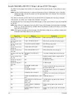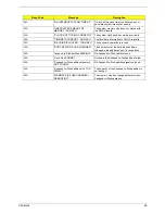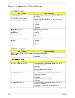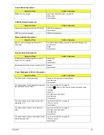
52
Chapter 3
8.
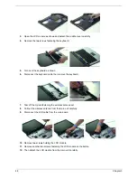
Detach the VGA thermal from the VGA board.
9.
Disconnect the modem cable from the main board.
10.
Remove the two screws fastening the modem board as shwon.
11.
Disconnect the modem board from the main board.
12.
Disconnect the modem cable from the modem board.
13.
Remove the two screws holding the speaker set to the lower case.
14.
Take out the speaker set from the lower case. This completes the main unit disassembly.
Содержание Aspire 5500
Страница 6: ...VI ...
Страница 14: ...6 Chapter 1 JP23 Modem Cable Connector JP39 ODD Connector ...
Страница 36: ...28 Chapter 1 ...
Страница 48: ...40 Chapter 2 ...
Страница 57: ...Chapter 3 49 ...
Страница 81: ...Chapter 5 73 JP19 RJ11 RJ45 JP31 DDR2 Socket JP23 Modem Cable Connector JP39 ODD Connector ...
Страница 82: ...74 Chapter 5 ...
Страница 84: ...76 Chapter 6 Exploded Diagram The System 011 012 013 ...
Страница 85: ...Chapter 6 77 Upper Case Assembly ...
Страница 86: ...78 Chapter 6 Lower Case Assembly ...
Страница 87: ...Chapter 6 79 LCD Module ...
Страница 88: ...80 Chapter 6 HDD Module ODD Module ...
Страница 103: ...Index 104 ...

