Chapter 3
68
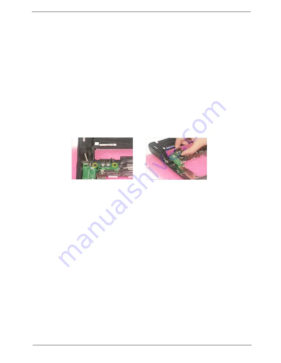
Removing the DC Board
1.
See “Removing the Battery” on page 50.
2.
See “Removing the Middle Cover” on page 54.
3.
See “Removing the Keyboard” on page 61.
4.
See “Removing the Upper Case Assemly” on page 63.
5.
See “Removing the Middle Cover Hook /Fan” on page 61.
6.
See “Removing the Thermal Module” on page 62.
7.
See “Removing the VGA Thermal Plate” on page 64.
8.
See “Removing the CPU Heatsink Plate” on page 65.
9.
See “Removing the Second Fan Bracket” on page 65.
10.
See “Removing the ODD Module(2)” on page 66.
11.
See “Removing the HDD Bracket” on page 66.
12.
See “Removing the Main Board” on page 67.
13.
Remove the two screws that fasten the DC board. Then detach the DC board from the lower case.
Removing the I/O Port Bracket
1.
See “Removing the Battery” on page 50.
2.
See “Removing the Middle Cover” on page 54.
3.
See “Removing the Keyboard” on page 61.
4.
See “Removing the Upper Case Assemly” on page 63.
5.
See “Removing the Middle Cover Hook /Fan” on page 61.
6.
See “Removing the Thermal Module” on page 62.
7.
See “Removing the VGA Thermal Plate” on page 64.
8.
See “Removing the CPU Heatsink Plate” on page 65.
9.
See “Removing the Second Fan Bracket” on page 65.
10.
See “Removing the ODD Module(2)” on page 66.
11.
See “Removing the HDD Bracket” on page 66.
12.
See “Removing the Main Board” on page 67.
13.
Remove the four hex screws to detach the I/O port bracket from the main board.
Содержание Aspire 3010 Series
Страница 1: ...Aspire 3010 5010 Series Service Guide PRINTED IN TAIWAN ...
Страница 6: ...VI ...
Страница 35: ...Chapter 1 29 ...
Страница 60: ...Chapter 3 56 ...
Страница 100: ...Chapter 4 96 8 You will see the screen displaying PASS when the system has buit NAPP Master hard disc drive ...
Страница 101: ...97 Chapter 4 ...
Страница 105: ...101 Chapter 6 Aspire 3010 5010 Exploded Diagram ...


