


Chapter 7
87
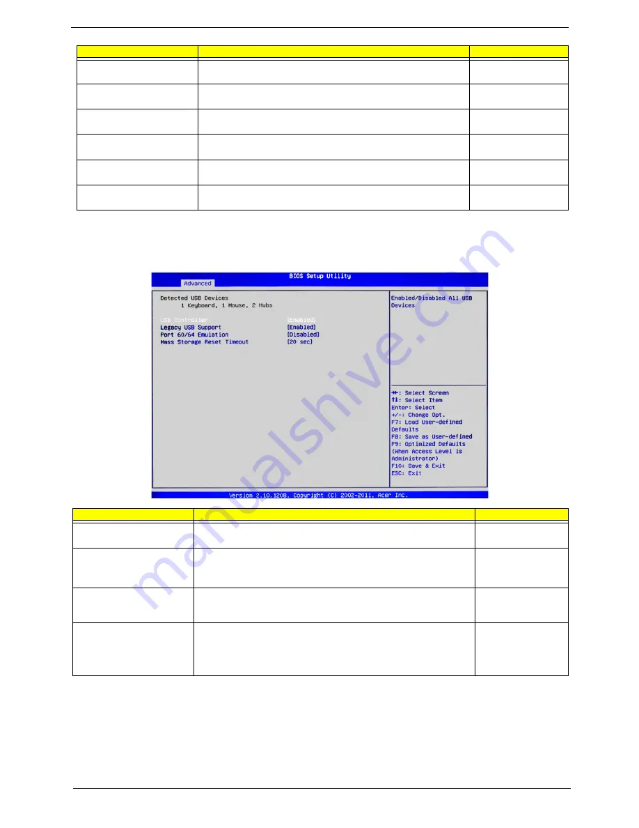
USB Configuration
When this submenu is selected, the BIOS automatically detects the all USB devices connected to the system
and displays the following items.
Onboard Graphics
Controller
Enables or disables the onboard graphics controller.
Enabled
Disabled
Primary Graphics
Sets the primary graphics to add-on or onboard.
ADD ON
Onboard
Onboard LAN Controller
Enables or disables the onboard LAN controller.
Enabled
Disabled
Onboard LAN I/O ROM
Enables or disables the onboard LAN I/O ROM.
Enabled
Disabled
Onboard LAN I/O ROM
Option
Sets the Onboard LAN I/O ROM option.
PXE
iSCSI
PCI ROM Priority
In case of multiple option ROMs (Legacy and EFI compatible),
specifies what PCI Option ROM to launch.
EFI Compatible ROM
Legacy ROM
Parameter
Description
Option
USB Controller
Enables or disables all USB devices.
Enabled
Disabled
Legacy USB Support
Select
Enabled
to use Legacy USB devices. If this item is set to Auto,
Legacy USB support will be automatically enabled if a legacy USB
device is installed in the system.
Enabled
Disabled
Auto
Port 60/64 Emulation
Enables I/O port 60h/64h emulation support. Enable this feature for
complete USB keyboard legacy support for non-USB aware operating
systems.
Enabled
Disabled
Mass Storage Reset
Timeout
This setting allows you to decide how long the system should wait in
an attempt to detect the presence of a USB Mass Storage Device
before it issues a start command the system to proceed with the next
operation during POST.
10 sec
20 sec
30 sec
40 sec
Parameter
Description
Option
Содержание AC100
Страница 1: ...AC100S Service Guide PART NO PRINTED IN TAIWAN ...
Страница 7: ...Chapter 1 1 Exploded view System components Chapter 1 ...
Страница 14: ...8 Chapter 3 Front inner view No Icon Component 1 Lock 2 HDD carriers 3 Power button ...
Страница 19: ...Chapter 3 13 System block diagram ...
Страница 20: ...14 Chapter 3 ...
Страница 40: ...34 Chapter 5 12 Pull out the mainboard tray completely ...
Страница 50: ...44 Chapter 5 3 Pull the power button cable module through the opening on the mainboard tray ...
Страница 77: ...Chapter 5 71 7 Close the front panel door ...
Страница 78: ...72 Chapter 5 ...
Страница 112: ...106 Chapter 8 ...


