background image

3.5.12 Resume by Ring

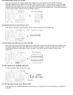
This option lets you specify enable or disable external Modem Wake Up function. The function of power on through modem
when system is off.
To select "Enabled" : To let the system to enter the environment of DOS or Windows 95/98 OS before system is power off. As
long as there are any massage through the Modem to enter the System during system is power off. The system will enable
power on function.

3.5.13 Resume by Alarm

Set this option to enable or disable the RTC Alarm to Wake Up the system which is set at soft Off.

3.5.14 Wake up on LAN

This allows you to remotely power up your system through your network by sending a wake-up frame or signal. With this
feature, you can remotely upload/download data to/from systems during off-peak hours. Set to Enabled to set this
feature.

3.5.15 Date (of Month) Alarm, Time (hh:mm:ss) Alarm

Set these options to specify the RTC Alarm time on Date / Hour / Minute / Second.

3.5.16 IRQ 8 Break Suspend

To enable or disable the detection of IRQ 8 (RTC) event for power down state transition.

3.5.17 IRQ[3-7, 9-15], NMI

To enable or disable the detection of IRQ 3-7, IRQ 9-15 or NMI interrupt events for power down state transition.

3.5.18 Primary/Secondary IDE 0/1, Floppy Disk, Serial & Parallel Port

These items enable or disable the detection of IDE, floppy, serial and parallel port activities for power down state transition.
Actually it detects the read/write to/from I/O port.

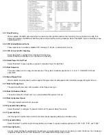
3.6 PNP/PCI Configuration Setup

ROM PCI / ISA BIOS (XXXXXXXX)

PNP/PCI CONFIGURATION

AWARD SOFTWARE, INC.

3.6.1 PNP OS Installed

This field allows you to use a Plug-and-Play (PnP) operating system. Please set it as " No"“ if the operating system has no PnP
function or to avoid reassigning the IRQs by the operating system.

3.6.2 Resources Controlled By

Default setting is "Auto". This setting allows the BIOS to self detect setting and Plug-and-Play devices during start up. The user
can select and configure IRQs under "Manual" mode.

3.6.3 Reset Configuration Data

In case a conflict occurs after you assign the IRQs or after you configure your system, you can enable this function to allow your
system to automatically reset your configuration and reassign the IRQs, DMAs, and I/O address.

Содержание 370LXA

Страница 1: ...d Layout Chapter 2 Hardware Setup 2 1 Installation Procedure 2 1 1 Jumper Setting 2 1 2 Clearing the CMOS 2 1 3 CPU Voltage Setting 2 2 Installation of CPU 2 3 Installation of Memory 2 3 1 Installation of 168 pin DIMM 2 3 2 Removal of 168 pin DIMM 2 3 3 Memory Configuration 2 4 I O Connections Panel Connections 2 4 1 ATX Power Connector 2 4 2 CPU Fan Connectors 2 4 3 Infrared Connector 2 4 4 Flopp...

Страница 2: ...GPset chipset DIMM Supports 3 3V EDO or SDRAM in 3 168 pin banks each bank consists of 1x168 pin 64 bit DIMM socket which can support memory sizes of 8 16 32 64 128 MB modules Supports up to a maximum of 384 MB with SDRAM 768 MB with EDO system memory IDE Dual channel PIO and PCI Bus Master IDE ports support up to 4 EIDE devices for HDD or CD ROM Supports PIO Mode 4 with data transfer rate up to 1...

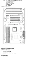
Страница 3: ... One IDE Ribbon Cable One Floppy Ribbon Cable One Driver diskette User s Manual 1 4 MotherBoard Layout Chapter 2 Hardware Setup 2 1 Installation Procedure 1 Jumper setting BIOS 2 Installation of CPU 3 Installation of Memory 4 I O Connections Panel Connections 2 1 1 Jumper Setting ...

Страница 4: ...rn on the power 7 While the system reboots press DEL key to set the BIOS setup 2 1 3 CPU Voltage Setting The motherboard supports Socket 370 CPU VID function the CPU core voltage is automatically detected the range is from 1 3V to 2 0V 2 2 Installation of CPU Before installing CPU make sure the power is off Locate the level bar on the PGA370 ZIF socket Push level bar away from the socket and pull ...

Страница 5: ...8MB 2 4 I O Connections Panel Connections I O Connections J2 ATX Power Connector JFAN1 CPU fan connector JIR1 IrDA Connector Cable optional JFLP1 Floppy Disk Drive Connector IDE1 2 Primary Secondary IDE Connectors JMOUSE1 PS 2 Mouse Port JKB1 PS 2 Keyboard Connector JCOM1 2 Serial Ports 1 2 JPRT1 Printer Port USB1 2 USB Connector JWOL Wake up on LAN connector SB_LINK For link with Creative s Sound...

Страница 6: ...onnector 34 pin JFLP1 This connector supports the provided floppy disk drive ribbon cable Orient the red stripe to pin 2 4 5 Primary Secondary IDE Connector Two 40 pin IDE These connectors support the provided IDE hard disk ribbon cable Connect your first IDE hard disk to master mode of the primary channel If you have second IDE device to install in your system connect it as slave mode on the same...

Страница 7: ... 4 11 Wake up on LAN Connector 3 pin JWOL The connector powers up the system when a wakeup packet or signal is received from the network This feature requires the Wake up on LAN function in BIOS is set to Enabled and that your system has an ATX power supply with at least 720mA 5V standby power 2 4 12 Creative s SB_LINK Sound Connector 6 pin SB_LINK The SB_LINK serves as a bridge between the mainbo...

Страница 8: ...rner of your screen When you enter the CMOS Setup Utility the Main Menu will be displayed Figure 3 1 You can use arrow keys to select your function press Enter key to accept the selection and enter the sub menu Figure 3 1 CMOS Setup Utility Main Screen ROM PCI ISA BIOS XXXXXXXX CMOS SETUP UTILITY AWARD SOFTWARE INC 3 2 Standard CMOS Setup With the sub menu Figure 3 2 you can setup the system date ...

Страница 9: ...drive and CD ROM drive at the POST stage If your hard disk drive is a SCSI device please select None for your hard drive setting 3 2 4 Floppy Drives A B Setting Select your floppy disk drive type Options are 360KB 5 25 720KB 3 5 1 2MB 5 25 1 44MB 3 5 2 88MB 3 5 3 2 5 Video Display Adapter Setting Select the display adapter type for your system Options are EGA VGA MONO CGA40 and CGA80 3 2 6 Halt On...

Страница 10: ... 6 Swap Floppy Drive When enabled physical drive A will be assigned to logical drive B and physical drive B will be assigned to logical drive A 3 3 7 Boot Up Floppy Seek The system will detect and verify operation of the floppy drive type 3 3 8 Boot Up Numlock Status The option allows the NumLock key to be activated after system boot up 3 3 9 Boot Up System Speed This option selects system boot up...

Страница 11: ...IPSET FEATURES SETUP SCREEN ROM PCI ISA BIOS XXXXXXXX CHIPSET FEATURES SETUP AWARD SOFTWARE INC 3 4 1 Auto Configuration The optimum value for the chipset and CPU will be automatically loaded when enabled 3 4 2 DRAM Speed Selection This option must match the memory speed If the installed memory is 60ns type you should set it to 60 3 4 3 EDO RAS To CAS Delay These are timing of EDO CAS Latency and ...

Страница 12: ...16 32 64 128 256MB Memory mapped graphics data structures can reside in the Graphics Aperture 3 4 14 SDRAM RAS to CAS Delay These are timing of SDRAM CAS Latency and RAS to CAS Delay Calculated by clocks They are important parameters affects SDRAM Performance 3 4 15 SDRAM RAS Precharge Time The RAS precharge means the timing to inactive RAS and the timing for DRAM to do precharge before next RAS c...

Страница 13: ...he DPMS feature 3 5 5 Video Off After This option allows your monitor to blank after your system went into Doze Standby or Suspend mode You can elect to not blank screen by select N A Default value is Standby 3 5 6 Doze Mode When system is inactive after the predefined time limit system performance will drop down This is the first level of Power Management 3 5 7 Standby Mode System turns off the v...

Страница 14: ...RTC event for power down state transition 3 5 17 IRQ 3 7 9 15 NMI To enable or disable the detection of IRQ 3 7 IRQ 9 15 or NMI interrupt events for power down state transition 3 5 18 Primary Secondary IDE 0 1 Floppy Disk Serial Parallel Port These items enable or disable the detection of IDE floppy serial and parallel port activities for power down state transition Actually it detects the read wr...

Страница 15: ... a memory space for non PnP compatible ISA card 3 6 9 Assign IRQ For USB Default is Enabled You can disable this item when you do not attach any USB devices on board and need extra IRQ for other device The yellow exclamation mark will be shown in System Device Manager under Windows 95 98 if you disable this item This is a normal status 3 7 Integrated Peripherals You can control Input and Output fu...

Страница 16: ...settings To modify highlight Supervisor Password or User Password and press the Enter key The screen will prompt you Enter Password Enter your password The maximum size of the password is 8 characters System will prompt you to reenter the password to verify Remember the passwords are case sensitive If you want to remove the passwords either delete passwords or press Enter when prompting for new pa...

Отзывы: