background image

Disassembly

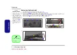
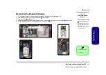
2 - 24 Removing the Hard Disk from the Secondary HDD Bay

2.Disassembly

1.

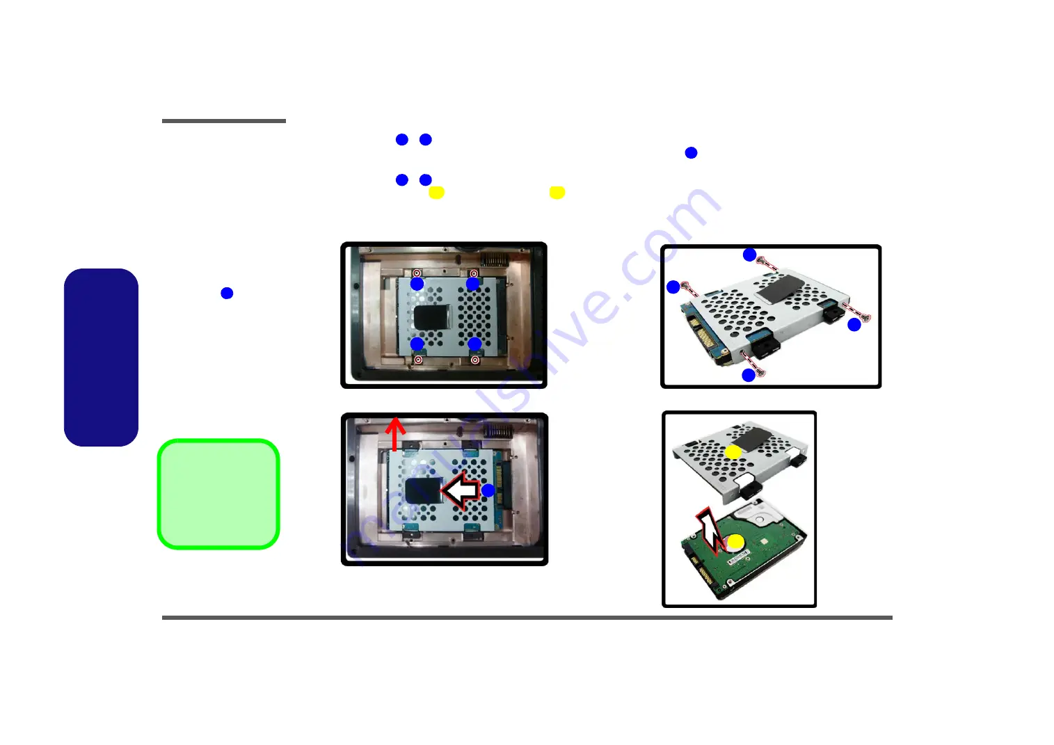
Remove screws 

 - 

 from the hard disk assembly


(

Figure 19

a

)

.

2.

Grip the tab and slide the hard disk assembly in the direction of the arrow 


(

Figure 19b

).

3.

Lift the hard disk assembly out of the compartment (

Figure 19b

).

4.

Remove screws 

 - 

 from the hard disk assembly (

Figure 19c

).

5.

Separate the hard disk 

 from the HDD case 

 (

Figure 19d

).

6.

Insert the replacement HDD into the case 

*Make sure the cable connector is facing towards the rear of the

case as illustrated below

.

1

4

5

1

2

5

3

4

6

7

8

9

a.

b.

c.

d.

11

10

Figure 19

Removing the 

Hard Disk from the 

Secondary HDD 

Bay 

a. Remove screws from

the hard disk assem-
bly.

b. Grip the tab and slide

the hard disk assem-
bly in the direction of
the arrow 

.  Lift the

hard disk assembly
out of the compart-
ment.

c. Remove screws from

the hard disk assem-
bly.

d. Separate the HDD

from the HDD case.

5

10. Hard Disk
11. Hard Disk Case

8  Screws

6

9

10

11

www.acecomputers.com

Содержание Mustang W650R

Страница 1: ......

Страница 2: ...io Features 1 15 HDMI Ports 1 16 Driver Installation 1 19 Wireless LAN Module 1 21 PC Camera 1 22 USB TV Tuner Module 1 24 Intel Turbo Memory Module 1 25 Fingerprint Reader 1 26 Bluetooth Configuratio...

Страница 3: ...setup If they aren t or you are planning to re configure or re install portions of the system refer to the expanded User s Manual The Device Drivers Utilities User s Manual disc does not contain an o...

Страница 4: ...ed power sup ply If you are unsure of your local power specifications consult your service representative or local power com pany The AC DC adapter may have either a 2 prong or a 3 prong grounded plug...

Страница 5: ...operating instructions If the computer has been dropped or damaged do not touch the poisonous liquid if the LCD panel breaks If there is an unusual odor heat or smoke coming from your computer Cleanin...

Страница 6: ...the computer Note Never lift the computer by the lid LCD 7 Press the power button to turn the computer on System Software Your computer may already come with system software pre installed Where this...

Страница 7: ...D 0 at lease two hard disks needed Identical drives reading and writing data in paral lel to increase performance RAID 0 imple ments a striped disk array and the data is broken into blocks and each bl...

Страница 8: ...Changes from the Exit menu or press F10 and press Enter to exit the BIOS and reboot the computer Part II Intel Matrix 1 Press Ctrl i to enter RAID configuration menu Figure 2 Intel R Matrix Storage Ma...

Страница 9: ...l now return to the main menu Figure 3 RAID Created 11 Select 5 Exit and press Enter then press Y to exit the RAID configuration menu 12 Make sure the Windows 10 OS USB Stick is in a USB port and as t...

Страница 10: ...ader Module 11 LCD Panel Color LED 11 Wireless Device Operation Aboard Aircraft The use of any portable electronic transmission de vices e g WLAN or Blue tooth aboard aircraft is usually prohibited Ma...

Страница 11: ...ions visual indica tors are available when the hot key driver is installed Keys Function Visual Indicators Keys Function Visual Indicators Fn Play Pause in Audio Video Programs Fn F7 Display Toggle Fn...

Страница 12: ...stant Keys Icon Color Description Green Hard Disk Activity Green Number Lock Numeric Keypad Acti vated Green Caps Lock Activated Green Scroll Lock Activated Green The Computer is On Blinking Green The...

Страница 13: ...A Port 10 Mini IEEE 1394 Port 11 HDMI In Port 12 8 in 1 Card Reader 13 Optical Device Drive Bay 14 Line In Jack 15 S PDIF Out Jack 16 Microphone In Jack 17 Headphone In Jack 18 USB 2 0 Ports 19 Securi...

Страница 14: ...U in any way may violate your warranty Overheating To prevent your com puter from overheating make sure nothing blocks any vent while the computer is in use 3 2 1 1 4 6 5 Battery Information Always co...

Страница 15: ...you can right click the desktop and select Screen resolution 5 Use the dropbox to select the screen Resolution 6 Click Advanced settings To access the NVIDIA Control Panel 1 Click Start and click All...

Страница 16: ...mbination to tog gle through display options when SLI is enabled SLI supports only a Single display and attempting to config ure dual displays may cause an error Use the NVIDIA Control Panel to select...

Страница 17: ...Create a power plan in the left menu and select the options to create a new plan Click Change Plan Settings and click Change advanced power settings to access further con figuration options Audio Fea...

Страница 18: ...external sources such as Blu ray players DVDs set top boxes and games consoles etc on your computer screen GameMate Media Player HDMI In The GameMate Media Player allows you to play content from digit...

Страница 19: ...edia Play er CyberLink Power DVD a background noise can oc cur If this situation does arise then please follow the instructions below 1 Click Start and click Control Panel or point to Settings and cli...

Страница 20: ...ct 5 1 Speaker from the Speaker Configuration pull down menu Figure 13 Speaker Configuration 5 Plug the front speaker cables into the Headphone Out Jack 6 Plug in the cables you may require an adapter...

Страница 21: ...and browse to the executable file in the ap propriate driver folder If a Found New Hardware wizard appears during the in stallation procedure click Cancel and follow the instal lation procedure as dir...

Страница 22: ...ouchpad Driver Yes 2 Click Next 3 Click the button to accept the license and click Next 4 Click Finish Restart Now to restart the computer USB 3 0 1 Click 6 Install USB 3 0 Driver Yes 2 Click Next 3 C...

Страница 23: ...g to a Wireless Network The operating system is the default setting for Wireless LAN control in Windows Make sure the Wireless LAN module is turned on 1 Click the taskbar wireless icon and then double...

Страница 24: ...it is necessary to setup the audio recording options in Windows 1 Click Start and click Control Panel or point to Settings and click Control Panel 2 Click Sound Hardware and Sound 3 Click Recording ta...

Страница 25: ...ation then click Open then set the Capture file size and click OK You can then start the capture process as above Reducing Video File Size Note that capturing high resolution video files requires a su...

Страница 26: ...s Media Center 1 Run Windows Media Center directly from the Start menu Start Programs Windows Media Center 2 Windows Help and Support provides information on the Windows Media Center functions Click S...

Страница 27: ...n as Optane flash memory is an Intel technology that re duces the time it takes for a computer to boot up to load applications and to write data to the hard drive Intel Turbo Memory Matrix Storage Set...

Страница 28: ...d to do so note If you have not set a password Protector Suite QL cannot secure access to your computer 4 Click Submit when you have entered password 5 You will then be prompted to enroll your fingerp...

Страница 29: ...kbar 3 You can then do any of the following to access the Bluetooth Devices control panel Double click the icon to access the Bluetooth Devices control panel Click Right click the icon and choose an o...

Страница 30: ...uetooth module after the computer resumes from Sleep The Wireless LAN indicators show that the WLAN module is powered on however the module does not connect The WLAN module is turned off in the Window...

Страница 31: ...0 GHz 8 Cores 8 Threads 12M L3 Cache 14nm LGA1151 Package i7 9700 3 20 GHz 8 Cores 8 Threads 12M L3 Cache 14nm LGA1151 Package i5 9500 3 20 GHz 6 Cores 6 Threads 9M L3 Cache 14nm LGA1151 Package LCD 1...

Страница 32: ...ory Module Interface Three USB 2 0 Ports Two USB 3 0 Ports One eSATA Port One HDMI Out Port One HDMI In Port One DVI Out Port One S PDIF Out Jack One Headphone Speaker Out Jack One Microphone In Jack...

Страница 33: ...the disassembly process easier each section may have a box in the page margin Information contained under the figure will give a synopsis of the sequence of procedures involved in the disassembly pro...

Страница 34: ...nnection make sure the connector is oriented in the same way The pin1 side is usually not indicated Pressure sockets for multi wire connectors To release this connector type grasp it at its head and g...

Страница 35: ...l on the wire 6 Peripherals Turn off and detach any peripherals 7 Beware of static discharge ICs such as the CPU and main support chips are vulnerable to static electricity Before handling any part in...

Страница 36: ...page 2 5 2 Remove the video card page 2 9 3 Install the video card page 2 11 To remove the Keyboard 1 Remove the battery page 2 5 2 Remove the keyboard page 2 12 To remove the Wireless LAN Module 1 Re...

Страница 37: ...ver 2 Loosen screws Figure 1a and carefully lift the battery up Figure 1b 3 Remove the battery from the battery bay Figure 1c 4 Battery 3 Screws 1 3 6 4 6 4 a 4 b 2 3 1 c 4 Figure 1 Battery Removal a...

Страница 38: ...4 Remove the screw at point Figure 2c and use a screwdriver to carefully push out the optical device at point Figure 2d 5 Reverse the process to install any new optical device Figure 2 Optical Device...

Страница 39: ...U fan c Disconnect the fan cable and remove the CPU fan d Remove the screws from the CPU heatsink Heat Sink Screw Removal and Insertion Remove the screws from the heat sink in the order indicat ed her...

Страница 40: ...new CPU 11 When re inserting the CPU pay careful attention to the pin alignment it will fit only one way DO NOT FORCE IT 18 19 20 21 22 23 23 Figure 4 Processor Removal cont d e Carefully lift up the...

Страница 41: ...ards 20 Screws Caution The heat sink and video card area in general contains parts which are subject to high tempera tures Allow the area time to cool before re moving these parts Figure 5 Video Card...

Страница 42: ...6f Figure 6 Video Card Removal cont d e The video cards will pop up f Disconnect the video card cables and re move the video cards 29 30 31 32 29 30 29 30 Video Cards Caution The heat sink and video c...

Страница 43: ...as it will go none of the gold colored contact should be showing DO NOT FORCE the card it should fit without much pressure 6 Secure the card with screws Figure 5 on page 2 9 7 Place the heat sink back...

Страница 44: ...snap up the LED cover module from point on the right Figure 8b 4 Disconnect cable and remove the LED cover module Figure 8c 1 3 4 6 LED Cover Module 3 Screws 5 6 Figure 8 Keyboard Removal a Remove scr...

Страница 45: ...12 12 13 14 14 Keyboard 5 Screws d f e 7 8 9 13 12 11 10 14 Keyboard Tabs Re Inserting the Keyboard When re inserting the keyboard align first the four keyboard tabs Figure 9f that are located at the...

Страница 46: ...of the arrow Figure 10h 10 Remove the keyboard shielding plate Figure 10i 15 17 18 19 18 g h 2 1 15 17 i 16 18 19 18 Figure 10 Keyboard Removal cont d g Remove screws from the keyboard shielding plat...

Страница 47: ...rated by arrow below and press it down into position Figure 11a 2 Secure the plate with screws Figure 11b Figure 11 Keyboard Shielding Plate Insertion a When re inserting the keyboard shielding plate...

Страница 48: ...rom the module socket Figure 12b 4 The Wireless LAN module Figure 12c will pop up 5 Lift the Wireless LAN module Figure 12d up and off the computer Figure 12 Wireless LAN Module Removal a The Wireless...

Страница 49: ...rew Figure 13b 4 Carefully separate the Bluetooth module from the connector and disconnect the cable Figure 13b 5 Lift the Bluetooth module Figure 13c up and off the computer Figure 13 Bluetooth Modul...

Страница 50: ...les will be visible at points Figure 14a 3 Gently pull the two release latches on the sides of the memory socket in the direction indicated by the arrows Figure 14b 4 The RAM module will pop up Figure...

Страница 51: ...only fit one way Make sure the module is seated as far into the slot as it will go DO NOT FORCE the module it should fit without much pressure 8 Press the module in and down towards the mainboard unti...

Страница 52: ...en setting up a new hard disk 1 Turn off the computer remove the battery page 2 5 and hard disk bay cover page 2 6 2 Remove screws from the hard disk assembly Figure 15a 3 Disconnect cable from the ha...

Страница 53: ...crews Figure 16d The number and sequence of screws to be removed will depend on whether or not you have one or two hard disks installed in the case 8 11 9 8 11 10 9 8 11 10 d Figure 16 Removing the Ha...

Страница 54: ...Make sure the cable connectors are facing towards the gap at the rear of the case 2 Insert screws to secure the hard disk s in the case Figure 17b 1 2 3 6 2 3 3 4 5 6 3 4 5 6 a b 2 1 1 2 Figure 17 In...

Страница 55: ...t an angle 5 Firmly connect cable to the mainboard and then secure the assembly with screws Figure 18d Removing the Hard Disk from the Secondary HDD Bay 7 8 9 7 10 13 9 11 10 12 c d 7 8 7 7 13 Figure...

Страница 56: ...D case Figure 19d 6 Insert the replacement HDD into the case Make sure the cable connector is facing towards the rear of the case as illustrated below 1 4 5 1 2 5 3 4 6 7 8 9 a b c d 11 10 Figure 19 R...

Страница 57: ...traight down do not insert the assembly at an angle and then slide it in the direction of the arrow to lock in place Figure 20e 6 9 12 12 e Figure 20 Removing the Hard Disk s from the Secondary HDD Ba...

Страница 58: ...c 4 Remove screws at the base of the LCD assembly Figure 21c Figure 21 Hinge Removal a Re insert the hinges into the top case b Raise the LCD to a 90 angle c Remove the whole LCD assembly again from t...

Страница 59: ...Disassembly Removing the Hinges 2 27 2 Disassembly 5 Remove hinges Figure 22d 8 9 Figure 22 Hinge Removal d Remove the hinges 8 9 Hinges d 8 9 www acecomputers com...

Страница 60: ...Disassembly 2 28 2 Disassembly www acecomputers com...

Отзывы: