Manual PCI-A12-16A
26
Programming
On the card, the 8254 counters occupy the following addresses:
Base A 8:
Read/Write Counter #0
Base A 9:
Read/Write Counter #1
Base A A:
Read/Write Counter #2
Base A B:
Write to Counter Control register
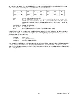
The counters are programmed by writing a control byte into a counter control register at Base A B.
The control byte specifies the counter to be programmed, the counter mode, the type of read/write operation,
and the modulus. The control byte format is as follows:
Base + B Write:
Counter Control Byte
B7 B6 B5 B4 B3 B2 B1 B0
SC1 SC0 RW1 RW0 M2 M1 M0 BCD
SC0-SC1: These bits select the counter that the control byte is destined for.
SC1
SC0
Function
0
0
Program Counter #0
0
1
Program Counter #1
1
0
Program Counter #2
1 1 Read/Write
Cmd.*
* See section on Reading and Loading the Counters.
RW0-RW1: These bits select the read/write mode of the selected counter.
RW1
RW0
Counter Read/Write Function
0
0
Counter Latch Command
0
1
Read/Write LS Byte
1
0
Read/Write MS Byte
1
1
Read/Write LS Byte, then MS Byte


