


Montageanleitung Instruction de montage
Assembly guide
Guida di montaggio
Instruccion de montaje
Montageaanwijzing
Seite 4 von 7
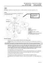
It might be necessary
to drill new holes in
the lid.
Attention:
Mount the casing prior to connecting the unit to the flue!
Contents:
Check the contents of the package against the
list below and inspect for damaged items.
-
Lid
1
-
Side panel
2
-
Bag containing screws
-
Rear wall
3
-
Front panel
4
(optional, separately packed)
-
Boiler control panel
5
(delivered inside
combustion chamber)
Assembly instructions
-
Place the lid
1
on the pins
6
on the boiler body.
-
Place the boiler control panel
5
on the lid and introduce the probes through the lid opening and into the sleeves.
Please refer to the enclosed instructions for detailed information on the boiler control panels.
-
Introduce burner control cable
8
through the lower opening, push it in and then feed it upwards along the left
hand side of the boiler body. Then, insert the cable through the lid opening
1
into the boiler control panel. Finally,
fasten cables at an adequate length (in such a way that the connectors on the burner have to be pulled to open
the door) in the holes provided in the opening using the cable clamp
9
. Insert remaining control panel cables
through the opening and push them into the raceway towards the back.
-
Insert the control panel into the foreseen support.
-
Fold the tongues at the bottom of the side panels
2
by 90° towards the front. These serve as stops for the mag-
nets of the front panel.
-
Snap the side plates
2
to the lid and fasten them to boiler feet with washers
10
and screws
11.
-
Fold the tongue of the rear panel
3
by 90° towards the front.
-
Fasten the rear panel
3
to the lid and side panels with the screws provided
7
.
-
Snap the front panel
4
to the front part of the lid and slide it downwards between the side plates until the magnets
click to the stops.


