


21
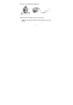
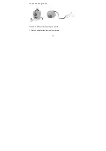
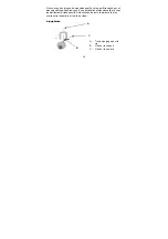
2. Connect the video cable (recommended cable type: RG59) with the
BNC video output (1) of the camera and with the output of the camera
as the next connected device.
The maximum cable length must not exceed 100 m.
3. Connect a 12V DC voltage supply to the power input of the camera (2).
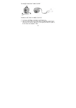
4. Hold the camera at the location where you want to mount it later. Check
the orientation and angle of the camera.
5. Fasten the supplied wall or ceiling mount to the desired installation
location and screw the mount into the camera housing.
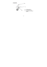
6. Change the orientation of the camera holder if necessary by slightly
loosening the fixing screw (B/C) and changing the position as required.
Then tighten the fixing screw so that the camera remains in the desired
position.
Содержание TV7510
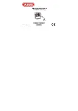
Страница 12: ...Video surveillance camera Installation guide TV7510 TV7511 TV7512 Version 1 3 03 2011 ...
Страница 19: ...19 6 Installation C A B A Lock screw hole B Fixing bracket screw C Fixing screws for camera module ...
Страница 23: ...Caméra vidéo de surveillance Instructions d installation TV7510 TV7511 TV7512 Version 1 3 03 2011 ...
Страница 33: ...Video bewakingscamera Installatiehandleiding TV7510 TV7511 TV7512 Version 1 3 03 2011 ...
Страница 44: ...Videoovervågningskamera Installations Guide TV7510 TV7511 TV7512 Version 1 3 03 2011 ...
Страница 52: ...52 Pan Tilt kan drejes 360 Installer kameraet som følger 1 Vælg et egnet sted for kamera placeringen ...


