


390248 5
/0
6
ABUS - Das gute Gefühl der Sicherheit
www.abus.com
D
Technische Änderungen vorbehalten. Für Irrtümer und Druckfehler keine Haftung. ABUS © 2006
G
Subject to technical alterations. No liability for mistakes and printing errors. ABUS © 2006
D
Montage mit Poweranker:
Die mitgelieferte Unterlage ist gleichzeitig die Bohrschablone.
Durch Bohrung B mit Forstnerbohrer Ø 20,0 mm Kunststoffscheibe
durchbohren.
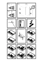
1. Bohrschablone auf Türblatt legen: bei Falzstärke unter 15 mm mit
der offenen Seite in den Raum zeigend (Abb. 4.1), bei Falzstärke ab
15 mm mit der geschlossenen Seite in den Raum zeigend (Abb. 4.2).
Pfeilspitzen lt. Abb. 4.1 und 4.2 mit der Mittellinie der Scharnier-
achsen in eine Flucht bringen. In dieser Stellung die Türblattkante
mit Bleistiftlinie oben und unten an der Bohrschablone anzeichnen.
2. Bohrschablone entlang der Türblattkante bis in die gewünschte
Montageposition vorschieben und anhand der Bleistiftmarkierungen
am Türblatt ausrichten (Abb. 5.1 und 5.2).
Bohrschablone in gewünschter Position mit 2 Schrauben durch die
2 Langlöcher (D) anschrauben und ausrichten. Durch Bohrung B
(mit Forstnerbohrer Ø 20,0 mm) 20 mm tief in den Rahmen bohren.
Löcher A und C Ø 3,5 mm vorbohren (Abb. 5.1 und 5.2).
3. Poweranker gemäß Abb. 6.1 und 6.2 einsetzen und ggf. ausrichten.
Achtung:
Pfeile müssen generell senkrecht zueinander zeigen
(Abb. 6.1 und 6.2).
4. Durch die Schrägbohrung des Ankers schräg in das Mauerwerk
120 mm tief bohren und Rahmendübel mit Schraube einsetzen und
festschrauben (Abb. 7).
Löcher A aufbohren (Holz und Kunststoff ohne Metalleinlage:
Ø 4,0 mm; Metall und Kunststoff mit Metalleinlage: Ø 4,5 mm).
Gummiring von Gelenkmodul entfernen
(Achtung: Teile als Satz zusammenhalten).
Gelenkmodul aufsetzen, durch die Löcher A mit Schrauben
Ø 5,5 x 50 mm anschrauben (Abb. 8).
Durch die Löcher F mit Schraube M6 x 30 mm festschrauben.
Abdeckhaube aufsetzen, fest andrücken und einrasten lassen
(Abb. 9.1 und 9.2).
Weitere Montage ab 6.
Montage ohne Poweranker:
Die mitgelieferte Unterlage ist gleichzeitig die Bohrschablone.
1. Bohrschablone auf Türblatt legen: bei Falzstärke unter 15 mm mit
der offenen Seite in den Raum zeigend (Abb. 4.1), bei Falzstärke ab
15 mm mit der geschlossenen Seite in den Raum zeigend (Abb. 4.2).
Pfeilspitzen lt. Abb. 4.1 und 4.2 mit der Mittellinie der Scharnier-
achsen in eine Flucht bringen. In dieser Stellung die Türblattkante
mit Bleistiftlinie oben und unten an der Bohrschablone anzeichnen.
2. Bohrschablone entlang der Türblattkante bis in die gewünschte
Montageposition vorschieben und anhand der Bleistiftmarkierungen
am Türblatt ausrichten.
Profitipp:
Zur besseren Fixierung der Bohrschablone 2 Stück
Schrauben 5,5 x 50 mm in Löcher E eindrehen bis die Schrauben-
spitzen leicht auf der Rückseite herausstehen. An richtiger Montage-
position diese Schraubenspitzen in den Türflügel drücken.
Die 6 Bohrungen A, B und C mit Ø 3,5 mm vorbohren (Abb. 5.1 und
5.2).
3. Die 4 Bohrungen A und B für das Gelenkmodul aufbohren
(Holz und Kunststoff ohne Metalleinlage: Ø 4 mm,
Metall und Kunststoff mit Metalleinlage: Ø 4,5 mm).
Sollte die Montage mit ABUS Befestigungsanker BA oder
ABUS IM 100 erfolgen (
in NL
ist ABUS BA durch SKG vorgeschrieben),
sind hierfür die Bohrungen B vorgesehen und es ist gemäß der
BA-Montageanleitung vorzugehen.
4. Gummiring von Gelenkmodul entfernen (Achtung: Teile als Satz
zusammenhalten). Mit 4 Schrauben 5,5 x 50 mm anschrauben
(Abb. 8). Abdeckhaube aufsetzen, fest andrücken und einrasten
lassen (Abb. 9.1 und 9.2).
Abb. 8a:
Montage Gelenkmodul (sollte dies einmal auseinanderfallen).
5. Vorderen Teil der Bohrschablone abbrechen oder abschneiden.
Hierdurch wird die Bohrschablone zur Unterlage (Abb. 10).
Abb. 10:
Bei Verwendung der Unterlage zur Schlossmontage
(Falzstärken von 0 –15 mm), muss der vordere Teil der Unterlage
(nach dem Vorbohren) an den eingekerbten Stellen abgebrochen
bzw. abgeschnitten werden.
6. Bei Türen mit Falzstärke 0 –15 mm: Führungsblech mit Unterlage
verwenden. Hierzu Führungsblech auf die geschlossenen Seite der
Unterlage legen (rastet ein). Bei Türen mit Falzstärke 15 – 30 mm:
Führungsblech ohne Unterlage verwenden.
Holztüren und Kunststofftüren ohne Metalleinlage: Führungsblech
mit 2 Schrauben 4,8 x 15 mm (ohne Unterlage) bzw. 4,8 x 32 mm
(mit Unterlage) durch die Langlöcher D nur leicht anschrauben
(Abb. 11.1 und 11.2), so dass sich das Führungsblech gerade noch
verschieben lässt.
Metalltüren und Kunststofftüren mit Metalleinlage:
Die beiden Bohrungen D auf 4 mm aufbohren und wie bei Holztüren
beschrieben weiterverfahren.
7. Führungsblech mit 2 selbstsichernden Schrauben M6 (Länge der
Schrauben lt. Tabelle aussuchen) mit dem Gelenkmodul leicht bis
zum Anschlag verschrauben und
Schrauben eine Umdrehung
zurückdrehen
(Abb. 12.1 und 12.2). Dann Führungsblech soweit
wie möglich in Richtung Tür (Griff) verschieben und Befestigungs-
schrauben (Langlochposition D) festdrehen.
Funktionskontrolle:
Tür muss problemlos zu öffnen sein.
Wenn nötig, Führungsblech verschieben. Danach Führungsblech
endgültig mit längstmöglichen Schrauben 4,8 x 32 mm und oder
4,8 x 50 mm verschrauben.
8. Abdeckhaube bis zum Anschlag aufschieben (Abb. 13.1 und 13.2)
oder von oben aufklipsen (Abb. 14.1 und 14.2).
VI. Bedienung:
TAS 112 bewegt sich beim Öffnen/Schließen wie ein Gelenk und
muss nicht ver- oder entriegelt werden und ist somit bedienfrei.
Die beweglichen Teile sollen von Zeit zu Zeit geschmiert werden.
Soll die Tür ausgehängt werden, müssen unbedingt die beiden
Schrauben M6 (aus Abb. 12) entfernt werden.
G
Installation with power anchor:
The underlay included also serves as the drilling template.
Drill through drill hole B with Forstner bit Ø 20.0 mm,
penetrating the plastic pane.
1. Place drill template on door leaf: if rebate width is less than 15 mm
with the open side facing the room (fig. 4.1), for rebate widths
starting from 15 mm with the closed side facing the room (fig. 4.2).
Align arrow points with the centre line of the hinge axes, as shown
in fig. 4.1 and 4.2. Mark the door leaf edge at the top and bottom
of the drill template in this position with a pencil.
2. Slide the drill template along the door leaf edge until it reaches the
desired position and align on the door leaf according to the pencil
markings (fig. 5.1 and 5.2).
Screw down and align drill template in desired position with 2 screws
through the 2 oblong holes (D). Drill to a depth of 20 mm through
drill marking B (with Forstner drill Ø 20.0 mm) into the frame.
Pilot-drill holes A and C Ø 3.5 (fig. 5.1 and 5.2).
3. Insert power anchor as shown in fig. 6.1 and 6.2 and align,
if required.
Please note:
Arrows generally need to point towards each other
vertically (fig. 6.1 and 6.2).
4. Drill through the anchor’s slanted bore hole into the masonry at
an angle and to a depth of 120 mmm, insert frame plug with screw
and screw down (fig. 7).
Bore open holes A (wood and synthetic materials without metal liner:
Ø 4.0 mm, metal and synthetic materials with metal liner:
Ø 4.5 mm). Remove rubber ring from joint module
(Caution: keep parts together as a set).
Set down joint module and screw on through holes A using
Ø 5.5 x 50 mm screws (fig. 8). Screw down through holes F with
screw M6 x 30 mm. Apply cover, press on firmly and allow to lock
into place (fig. 9.1 and 9.2).
Follow further installation instructions from step 6 onwards.
Installation without power anchor:
The underlay included in the delivery also serves as the drilling
template.
1. Place drill template on door leaf: if rebate width is under 15 mm with
the open side facing the room (fig. 4.1), for rebate widths starting
from 15 mm with the closed side facing the room (fig. 4.2).
Align arrow points with the centre line of the hinge axes, as shown
in fig. 4.1 and 4.2. Mark the door leaf edge at the top and bottom
of the drill template in this position with a pencil.
2. Slide the drill template along the door leaf edge until it reaches the
desired position and align on the door leaf according to the pencil
markings.
Professional advice:
For an optimal fixing of the drill template,
2 screws 5.5 x 50 mm screws into holes E until their points slightly
project through the back. Press these screw points into the door leaf
at the exact installation position.
Pilot-drill the six drill holes A, B and C with Ø 3.5 mm (fig. 5.1 and
5.2).
3. Bore open the 4 drill holes A and B for the joint module (wood and
synthetic materials without metal liner: Ø 4 mm, metal and synthetic
materials with metal liner: Ø 4.5 mm). If the installation is to be
carried out using ABUS fastening anchor BA or ABUS IM 100
(ABUS BA is prescribed by SKG in the Netherlands), use the drill
holes B dedicated to this purpose and proceed according to
BA installation instructions.
4. Remove rubber ring from joint module (caution: keep parts
together as a set). Screw down with 4 screws 5.5 x 50 mm (fig. 8).
Apply cover, press on firmly and allow to lock into place
(fig. 9.1 und 9.2).
Fig. 8a:
Joint module assembly (if it inadvertently comes apart).
5. Break or cut off front section of drill template.
This turns the drill template into an underlay (fig. 10).
Fig. 10: If the underlay is used for lock installation (rebate widths
from 0 –15 mm), the front section of the underlay needs to be cut
or broken off at the points marked with notches (after pilot-drilling).
6. For doors with a rebate width of 0 –15 mm: use guidance plate in
combination with underlay. To do this, place guidance plate on the
closed side of the underlay (locks into place). For doors with a rebate
width of 15 – 30 mm: use guidance plate without underlay.
Wooden and synthetic doors without metal liner: screw guidance
plate down lightly using 2 screws 4.8 x 15 mm (without underlay) or,
respectively, 4.8 x 32 mm (with underlay) through oblong holes D
(fig. 11.1 and 11.2), so that guidance plate can just about still be
moved.
Metal doors and synthetic doors with metal liner:
bore open both drill holes D to a depth of 4 mm and proceed as
proscribed for wooden doors.
7. Lightly screw together guidance plate and joint module with
2 self-locking screws M6 (see drilling table for screw lengths) up to
the stop and then
screw back screws one turn
(fig. 12.1 and 12.2).
Now slide guidance plate in direction of the door (handle)
and tighten fastening screws (oblong hole position D).
Function control:
door must be able to open easily.
Move guidance plate if necessary. Then finally screw down
guidance plate with the longest screws possible 4.8 x 32 mm
and or 4.8 x 50 mm.
8. Slide open cover until stop is reached (fig. 13.1 and 13.2)
or clip on from above (fig. 14.1 and 14.2).
VI. Operation:
TAS 112 moves like a joint when door is opened or closed, does
not require any bolting or unbolting and is hence operation-free.
Movable parts should be lubricated from time to time.
If the door is to be taken off its hinges, both screws M6 (see fig. 12)
unconditionally need to be removed.