background image

23

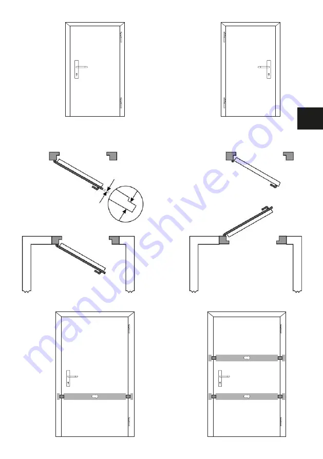
schéma 2

DIN à droite

Porte à feuillure

Épaisseur de feuillure

Épaisseur de feuillure

Porte affleur

DIN à gauche

Porte ouvrant vers l’intérieur

Porte ouvrant vers l’extérieur

schéma 3

schéma 4

FR

PR2700

PR2700

PR2700

Содержание PR2700

Страница 1: ...anzerriegel PR2700 Notice de montage et d utilisation Barre transversale blindée PR2700 DE FR www abus com Montage en gebruikshandleiding Deurbalk PR2700 Fitting and operating instructions Reinforced door bar PR2700 GB NL PR2700 6N026 ...

Страница 2: ...ntage pour les portes s ouvrant vers l intérieur 26 VII Instructions d utilisation 31 Accessoires spéciaux 32 Contents I Package contents 36 Individual parts 37 II General information 38 III Field of application of the PR2700 38 IV Fitting tools 40 V Replacing the door cylinder optional 40 VI Fitting instructions for doors that open inwards 42 VII Operating instructions 47 Special accessories 48 I...

Страница 3: ...820 Rahmendurchgangsverschraubung für Schließkästen PA1018 Befestigungsset für nach außen öffnende Tür DS10 Distanzscheiben 10 mm für Zylinderschutz Schlosskörperunterlage Holzplatte für eine verbesserte Montageposition bei nach außen öffnenden Türen sowie Stumpftüren ASP17 Anschraubplatte für Schließkästen I Packungsinhalt Packungsinhalt des PR2700 in Standardausführung s Abb 1 Pos Stückzahl Beze...

Страница 4: ...4 15 4 x 16 3 x 13 8 x 14 4 x 10 4 x 11 4 x 12 4 x 7 2 x 8 1 x 9 4 x 4 2 x 5 2 x 6 2 x 1 1 x 2 1 x 3 2 x Einzelteile Abb 1 ...

Страница 5: ...e durch einen speziell geschulten Facherrichter ausführen zu lassen III Einsatzmöglichkeiten des PR2700 Der PR2700 eignet sich für alle nach innen und außen öffnenden Falz und Stumpftüren DIN rechts oder DIN links Abb 2 Bei Türen mit Füllung und oder Leistenbesatz ist eine individuelle Anpassung vorzunehmen Die Standardausführung ist für nach innen öffnende Türen Türblattbreite von 735 mm bis 1030...

Страница 6: ...6 Abb 2 DIN rechts Falztür Falzdicke F a l z d i c k e Stumpftür DIN links Tür nach innen öffnend Tür nach außen öffnend Abb 3 Abb 4 PR2700 PR2700 PR2700 ...

Страница 7: ...kannten Türzylinder Bei Türblattstärken ab 50 mm und oder wenn der Türzylinder zu einer Schließanlage passen soll muss der Standard Türzylinder ausgewechselt werden Das Gleiche gilt wenn ohne Schließmöglichkeit von außen montiert werden soll 1 Neuen Türzylinder entsprechend DIN EN 1303 DIN 18252 und ggf Distanzscheiben und längere Schrauben beschaffen Bei Türblattstärke größer 50 mm Türzylinder gr...

Страница 8: ...fernen und zusätzliche Distanzscheibe n Tab 1 zwischen Zylinderschutz und Schlosskörper legen Mit Schrauben Tab 1 festschrauben 6 Getriebegehäuse wieder in die alte Montageposition Abb 6 ziehen und mit Schraube 1 locker fixieren 7 Zahnstangen entsprechend Abb 8 in Pfeilrichtung bis zum Anschlag schieben wobei die obere wieder einen Zahn zurückgeschoben werden muss 8 Türzylinder in umgekehrte Reihe...

Страница 9: ...rehen Anschlagschlitten festhalten Riegel eintourig zurückschließen Schlüssel abziehen Anschlagschlitten in Pfeilrichtung bis zum Anschlag schieben Anschlag schraube festdrehen Achtung Nicht überdrehen VI Montageanleitung für nach innen öffnende Türen Bei nach außen öffnender Tür bitte in der Montageanleitung des Sonderzubehörs PA1018 weiterlesen Vor der Montage bitte die Einstellung der Tür prüfe...

Страница 10: ... 10 Abb 13 Abb 12 Ø 4 2 x 22 mm Abb 11 3 Schlosskörper aufsetzen Zylinderrosette auf Türaußenseite aufstecken Abb 11 4 Schlosskörper entsprechend Abb 12 positionieren und waagerecht ausrichten Position der Befestigungsschrauben vorbohren Holz Ø 3 0 mm Metall Ø 3 5 mm und Schlosskörper mit Schrauben Ø 4 2 x 22 mm festschrauben Hinweis Bei Hohlraumtüren Ø 6 mm vorbohren beiliegende Spreizpatronen ei...

Страница 11: ...n markieren Bei festgelegter Riegelstellung Riegelstellschrauben 1 andrehen Es gilt a Auf festen Untergrund und gute Befestigungsmöglichkeiten achten besonders empfehlenswert ist es die Schließkästen auf dem Mauerwerk zu verankern b Schließkästen sollten unter Berücksichtigung von a möglichst nah an die Türkante montiert werden c Bei schmalen Türen kann eintouriges Schließen ausreichen s Kap V 8 d...

Страница 12: ...te beidseitig minus 3 15 mm anzeichnen und ablängen z B mit Eisensäge Abb 18 2 Riegelführungen aufdrücken und mit je 2 Schrauben 3 5 x 6 5 mm festklemmen Abb 19 Achtung Nicht überdrehen 3 Abdeckhaube auf den Schlosskörper aufdrücken Abb 20 Abb 19 1 3 2 Ø 3 5 x 6 5 mm Abb 20 Abb 18 3 15 mm Abb 18 ...

Страница 13: ...schrauben Ø 7 x 60 mm oder Dübel Ø 10 x 120 mm montieren Hierzu zwei schräge Bohrungen Ø 5 mm min 60 mm tief für Holzschrauben oder Ø 10 mm min 140 mm tief durch die Anschraubplatte hindurchbohren Holzschraube eindrehen oder Dübel mit Schraube komplett einsetzen und festschrauben 3 Zusätzlich durch die beiden Löcher für die Schließkastenbefestigung in Holz und Metall mit Ø 7 mm in Stein mit Ø 6 mm...

Страница 14: ...tstoffunterlagen an die angezeichnete Schließkasten position halten Bei Stumpftüren und Falzstärken 5 mm auf der Befestigungsposition Löcher Ø 20 mm 6 mm tief aufbohren Durch die beiden Befestigungslöcher Ø 10 mm min 140 mm tief für Rahmendübel hindurchbohren Dübel mit Schraube komplett ein setzen und festschrauben Sollten die Schrauben oder die Dübel keinen sicheren Halt finden empfehlen wir die ...

Страница 15: ...auben Abb 26 Wandschließblech auf die Rundbolzen aufsetzen Riegel bis zum Anschlag an die Wand ausschließen Befestigungspunkte 1 des Wand schließbleches anzeichnen Riegel zurückschließen Abb 27 Befestigungspunkte für das Wandschließblech Ø 6 mm vorbohren Dübel einsetzen und verschrauben Abb 27 Durch die beiden außen liegenden Befestigungslöcher 2 Ø 10 mm min 140 mm tief hindurchbohren Dübel mit Sc...

Страница 16: ...igungslöcher die bei entspre chender Riegelstellung zugänglich werden Ø 8 5 mm durchbohren von außen 13 15 mm 35 mm tief aufbohren und verschrauben Abb 29 PV1820 Befestigungsset mit Durchgangsverschraubung zur Befestigung der Schließkästen auf dem Türrahmen oder auf der Wand Abb 28 Es wird eingesetzt wenn die Schließkästen auf dem Türrahmen oder der Wand nicht stabil befestigt werden können Die Au...

Страница 17: ...Zylinderlänge Tabelle 1 Seite 7 muss die Stärke der Unterlage von 18 mm zur vorhandenen Türblattdicke hinzugerechnet werden Abb 30 Abb 30a Abb 30b Anschraubplatte ASP17 Die Anschraubplatte ASP17 eignet sich zur stabilen Befestigung der Schließkästen Sie kommt insbesondere dann zum Einsatz wenn der Untergrund nur unzureichende Möglichkeiten zur sicheren direkten Verankerung der Panzerriegel Schließ...

Страница 18: ...18 Notizen ...

Страница 19: ...Notice de montage et d utilisation Barre transversale blindée PR2700 FR PR2700 www abus com ...

Страница 20: ...r la gâche normale PV1820 Fixation à travers le cadre pour gâches PA1018 Kit de fixation pour porte ouvrant vers l extérieur DS10 Rondelles d écartement de 10 mm pour la protection du cylindre Support pour corps de serrure Panneau de bois pour améliorer la position de montage au niveau des portes s ouvrant vers l extérieur ainsi que les portes affleurantes ASP17 Plaque de fixation pour gâches I Co...

Страница 21: ...21 15 4 x 16 3 x 13 8 x 14 4 x 10 4 x 11 4 x 12 4 x 7 2 x 8 1 x 9 4 x 4 2 x 5 2 x 6 2 x 1 1 x 2 1 x 3 2 x Piéces schéma 1 FR ...

Страница 22: ...eur spécialement formé III Possibilités d utilisation de la PR2700 La barre PR2700 convient à toutes les portes affleurs ou à recouvrement ouvrant vers l intérieur et l extérieur DIN à droite ou DIN à gauche schéma 2 Une adaptation individuelle doit être effectuée dans le cas de portes à panneau et ou à baguettes La version standard convient aux portes ouvrant vers l intérieur largeur du battant 7...

Страница 23: ... droite Porte à feuillure Épaisseur de feuillure É p a i s s e u r d e f e u i l l u r e Porte affleur DIN à gauche Porte ouvrant vers l intérieur Porte ouvrant vers l extérieur schéma 3 schéma 4 FR PR2700 PR2700 PR2700 ...

Страница 24: ...ants de portes d une épaisseur minimale de 50 mm et ou lorsque le cylindre doit être intégré dans un système de fermeture organigramme le cylindre standard doit alors être remplacé La même chose est valable lorsque le montage doit être effectué sans possibilité de verrouillage de l extérieur 1 Acheter un nouveau cylindre de porte correspondant à la norme DIN EN 1303 DIN 18252 et le cas échéant des...

Страница 25: ...lusieurs rondelle s d écartement supplémentaire s Tab 1 entre la protection du cylindre et le boîtier Fixer le tout avec des vis Tab 1 6 Ramener le carter d engrenage dans son ancienne position de montage schéma 6 et le fixer légèrement avec une vis 1 7 Pousser les crémaillères selon schéma 8 dans le sens de la flèche jusqu à la butée celle du haut devant être repoussée d un cran en arrière 8 Remo...

Страница 26: ...êt refermer la barre d un tour retirer la clé Pousser le chariot d arrêt dans le sens de la flèche jusqu à la butée resserrer à fond la vis d arrêt Attention Ne pas forcer VI Instructions de montage pour porte ouvrant vers l intérieur Lorsque votre porte s ouvre vers l extérieur passez directement aux instructions de montage correspondant à l accessoire spécial PA1018 Avant de procéder au montage ...

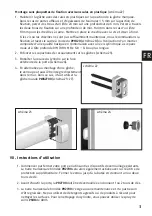
Страница 27: ...héma 12 Ø 4 2 x 22 mm schéma 11 3 Mettre en place le coffre emboîter la rosace du cylindre sur la face extérieure de la porte schéma 11 4 Positionner le coffre de la serrure selon schéma 12 et l orienter à l horizontale Percer les trous correspondant à la position des vis de fixation bois Ø 3 0 mm métal Ø 3 5 mm et visser à fond le coffre avec des vis d un Ø de 4 2 x 22 mm Remarque Dans le cas des...

Страница 28: ...quée visser les vis de réglage de la barre 1 Attention aux points suivants a Veiller à un support ferme et à de bonnes possibilités de fixation il est notamment recommandé d ancrer la gâche dans la maçonnerie b Les gâches doivent être montées le plus près possible de l arête de la porte c est en application du point a c Dans le cas de portes étroites une fermeture à un seul tour peut suffire voir ...

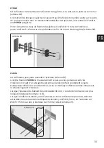
Страница 29: ...te des deux côtés en enlevant 3 15 mm ajuster à la longueur p ex avec une scie à métaux schéma 18 2 Enfoncer les guidages des pênes et les fixer avec pour chaque côté 2 vis de 3 5 x 6 5 mm schéma 19 Attention Ne pas forcer 3 Enfoncer le coffre sur le boîtier schéma 20 schéma 19 1 3 2 Ø 3 5 x 6 5 mm schéma 20 schéma 18 3 15 mm FR ...

Страница 30: ...e fixation avec 2 vis schéma 21 2 Installer une fixation supplémentaire monter les vis à bois d un Ø de 7 x 60 mm ou les chevilles d un Ø de 10 x 120 mm À cette fin percer deux forages à l oblique d un Ø de 5 mm sur min 60 mm de profondeur pour les vis à bois ou d un Ø de 10 mm sur min 140 mm de profondeur à travers la plaquette de fixation Visser la vis à bois ou mettre en place la cheville avec ...

Страница 31: ... la gâche marquée Dans le cas de portes affleurs et d épaisseurs de feuillures 5 mm sur la position de fixation percer des trous d un Ø de 20 mm sur une profondeur de 6 mm Percer à travers les deux trous de fixation sur une profondeur de min 140 mm dans le cas d un Ø de 10 mm pour les chevilles à cadre Mettre en place la cheville avec la vis et visser à fond Si les vis ou les chevilles ne sont pas...

Страница 32: ... la barre et visser à fond avec la vis de l accessoire PWA2700 schéma 26 Mettre en place la gâche murale sur les boulons ronds Déverrouiller les pênes jusqu à la butée contre le mur Dessiner les points de fixation 1 de la gâche murale Reverrouiller les pênes schéma 27 Percer les points de fixation pour la gâche murale d un Ø de 6 mm mettre en place les chevilles et les visser schéma 27 Percer à tr...

Страница 33: ...avers les trous de fixation disponibles devenus accessibles lors de la position adéquate de la barre un Ø de 8 5 mm de l extérieur un Ø de 13 15 mm sur une profondeur de 35 mm et visser schéma 29 PV1820 Kit de fixation traversante pour la fixation de la gâche sur la cadre de la porte ou sur le mur schéma 28 Ce kit est utilisé lorsque les gâches ne peuvent pas être fixées de manière stable sur le c...

Страница 34: ...vent être ainsi fixées dans la zone plus stable du cadre de porte de la maçonnerie schéma 30a Remarque afin de déterminer la longueur de cylindre nécessaire l épaisseur du support de 18 mm doit être ajoutée à l épaisseur du vantail existant schéma 30 schéma 30a schéma 30b Plaque de fixation ASP17 schéma 31 voir instructions de montage séparées ABUS ASP17 schéma 31 ...

Страница 35: ...35 Fitting and operating instructions Reinforced door bar PR2700 GB PR2700 www abus com ...

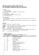
Страница 36: ...V1820 Frame passage screw connection for the lock cases PA1018 Fixing set for doors that open outwards DS10 Spacer discs 10 mm for cylinder protection Underlay for the lock body Wooden board enabling improved assembly position for doors that open outwards as well as flush doors ASP17 Mounting plate for lock casings I Package contents Package contents of the PR2700 in a standard design see Fig 1 Po...

Страница 37: ...37 15 4 x 16 3 x 13 8 x 14 4 x 10 4 x 11 4 x 12 4 x 7 2 x 8 1 x 9 4 x 4 2 x 5 2 x 6 2 x 1 1 x 2 1 x 3 2 x Individual parts Fig 1 GB ...

Страница 38: ...taller to execute the fitting III Field of application of the PR2700 The PR2700 is suitable for all hinged and unhinged doors that open inwards and outwards DIN right or DIN left Fig 2 Doors with panelling and or border trimmings must be individually adjusted use lock underlays if necessary The standard design is suitable for doors opening inwards door panel width of 735 mm to 1030 mm and door pan...

Страница 39: ...39 Fig 2 DIN right Hinged door Hinge thickness H i n g e t h i c k n e s s Unhinged door DIN left Door that opens inward Door that opens outward Fig 3 Fig 4 GB PR2700 PR2700 PR2700 ...

Страница 40: ...gths above 50 mm and or if the door cylinder has to fit in a locking system the standard door cylinder must be replaced The same applies if it is set to be fitted without any option to lock from outside 1 New door cylinders correspond to DIN EN 1303 DIN 18252 and obtain spacers and longer screws if required With door leaf strengths greater than 50 mm Obtain door cylinders of a greater length see t...

Страница 41: ...ction according to Fig 7 and place additional spacer disc s Tab 1 between the cylinder protection and the lock body Tighten with screws Tab 1 6 Pull the gear wheel housing into the old fitting position again Fig 6 and fix loosely with screw 1 7 Push toothed gear racks in the direction of the arrow fig 8 until they stop whereby the upper ones must be pushed back by one tooth 8 Reinstall the door cy...

Страница 42: ...ld stop slide close back the bar with one turn remove the key Push the stop slide in the direction of the arrow until it stops tighten stop screw Caution Do not overwind VI Fitting instructions for doors that open inwards For a door opening outwards please continue to read about special accessory PA1018 in the fitting manual Before fitting please check the door setting and properly set if required...

Страница 43: ...o Fig 10 Fig 9 Ø 51 55 mm Fig 10 Fig 13 Fig 12 Ø 4 2 x 22 mm Fig 11 3 Mount the lock body attach the escutcheon at door exterior Fig 11 4 Position lock body corresponding to Fig 12 Pre drill the position of the mounting screws wood Ø 3 0 mm metal Ø 3 5 mm and tighten the lock body with screws Ø 4 2 x 22 mm Note With cavity doors pre drill Ø 6mm use supplied bridging cartridge and tighten with Ø 4 ...

Страница 44: ...bar adjusting screws 1 when the door bar position has been set The following applies a Make sure that there is a stable subsurface and good attachment possibilities Anchoring the lock cases to the brickwork is especially recommended b Lock cases should be fitted as close as possible to the door edge taking a into account c One turn locking can suffice with narrow doors see chap V 8 d The door bar ...

Страница 45: ...5 mm on both sides according to the door frame width z B with a metal saw Fig 18 2 Press down the door bar guides and secure with 2 screws 3 5 x 6 5 mm Fig 19 Caution Do not overwind 3 Press down the cover onto the lock body Fig 20 Fig 19 1 3 2 Ø 3 5 x 6 5 mm Fig 20 Abb 18 3 15 mm Fig 18 GB ...

Страница 46: ...ig 21 2 For further reinforcement fit wooden screws with Ø 7 x 60 mm or dowels with Ø 10 x 120 mm For this purpose bore two bevelled holes with Ø 5 mm and a depth of at least 60 mm for the wooden screws or with Ø 10 mm and a depth of at least 140 mm through the screw on plate Screw in the wooden screw or insert the complete dowel with the screw and tighten 3 Drill out both holes for the lock case ...

Страница 47: ...c underlay onto the marked lock case position Drill out holes with Ø 20 mm and a depth of 6 mm for unhinged doors and a rebate 5 mm on the mounting position Bore through both mounting holes with Ø 10 mm and a depth of at least 140 mm for the frame dowels Insert dowel completely with the screw and tighten If the screws or the dowels cannot find a secure grip we recommend all through screw fittings ...

Страница 48: ...nt the wall strike plate onto the round bolts Lock the door bar onto the wall until the end stop Mark out the attachment points 1 of the wall strike plate Close back the door bar Fig 27 Pre drill the attachment points for the wall strike plate with Ø 6 mm insert the dowel and screw Fig 27 Drill through both of the external mounting holes 2 with Ø 10 mm and a depth of at least 140 mm Insert the com...

Страница 49: ...he existing mounting locks that are accessible depending on the door bar s position drill through Ø 8 5 mm drill out 13 15 mm and a depth of 35 mm and screw Fig 29 PV1820 Fixing set with all through screw fitting to attach the lock cases onto the door frames or on the wall Fig 28 It is used if the lock cases cannot be mounted to the door frames or wall in a stable manner The outer cover is visible...

Страница 50: ...the cylinder length required the underlay thickness of 18 mm must be added to the existing thickness of the door leaf Fig 30 Fig 30a Fig 30b Mounting plate ASP17 The ASP17 mounting plate is suitable for the sturdy fixing of lock casings It is used in particular when the options for anchoring the reinforced door bar lock casings directly and securely to the subsurface are inadequate Fig 31 see sepa...

Страница 51: ...51 Montage en gebruikshandleiding Deurbalk PR2700 NL PR2700 www abus com ...

Страница 52: ...zig is PV1820 Frame overgangsfitting voor sluitkommen PA1018 Bevestigingsset voor naar buiten draaiende deur DS10 Afstandsschijven 10 mm voor cilinderbescherming Opvulling voor slotbehuizing Houten plaat voor een betere montagepositie bij naar buiten openende deuren en opdekdeuren ASP17 Montageplaat voor sluitkom I Inhoud van de verpakking Inhoud van de verpakking van de PR2700 in standaarduitvoer...

Страница 53: ...53 15 4 x 16 3 x 13 8 x 14 4 x 10 4 x 11 4 x 12 4 x 7 2 x 8 1 x 9 4 x 4 2 x 5 2 x 6 2 x 1 1 x 2 1 x 3 2 x Afzonderlijke delen Afb 1 NL ...

Страница 54: ...ordoet bij de montage en of door verkeerd gebruik III Toepassingen van de PR2700 De PR2700 is geschikt voor alle naar binnen en buiten draaiende opdek en stompe deuren DIN rechts of DIN links afb 2 Bij massieve deuren en of opdeklijst dient een individuele aanpassing te worden uitgevoerd De standaarduitvoering is geschikt voor naar binnen draaiende deuren deurbladbreedte van 735 mm tot 1030 mm en ...

Страница 55: ...55 Afb 2 DIN rechts Opdekdeur Dikte sponning D i k t e s p o n n i n g Stompe deur DIN links Deur naar binnen draaiend Deur naar buiten draaiend Afb 3 Afb 4 NL PR2700 PR2700 PR2700 ...

Страница 56: ... een bladdikte vanaf 50 mm en of als de deurcilinder moet passen bij een sluitsysteem moet de standaard deurcilinder worden vervangen Hetzelfde geldt als er geen sluitmogelijkheid van buitenaf moet worden gemonteerd 1 Nieuwe deurcilinders volgens DIN EN 1303 DIN 18252 en eventueel afstandsringen en langere schroeven gebruiken bij deurbladdikte vanaf 50 mm Deurcilinder met een grotere lengte zie ta...

Страница 57: ...rwijderen en extra afstandsschijf schijven tab 1 tussen cilinderbescherming en slot leggen Met schroeven tab 1 vastschroeven 6 Behuizing weer in de oude montagepositie afb 6 trekken en met schroef 1 losjes vastzetten 7 De tandheugels volgens afb 8 in de richting van de pijl tot tegen de aanslag verschuiven en de bovenste een tand in de tegenovergestelde richting terugschuiven 8 Deurcilinder weer m...

Страница 58: ...te draaien Aanslagstelbout 6 uitdraaien de aanslagslede vasthouden de schoot door de sleutel een omwenteling te draaien intrekken de sleutel uitnemen De aanslagslede in de richting van de pijl tot tegen de aanslag schuiven de aanslagbout vastdraaien Let op Niet doldraaien VI Montagehandleiding voor naar binnen draaiende deuren Bij naar buiten openende deur doorlezen in de montage instructie van de...

Страница 59: ...0 Afb 13 Afb 12 Ø 4 2 x 22 mm Afb 11 3 Slot plaatsen cilinderslotplaat op de buitenzijde van de deur plaatsen Abb 11 4 Plaats het slot op de manier zoals is weergegeven in fig 12 Positie van de bevestigingsschroeven voorboren hout Ø 3 0 mm metaal Ø 3 5 mm en slot met schroeven Ø 4 2 x 22 mm vastschroeven Aanwijzing In holle deuren Ø 6 mm voorboren de meegeleverde expansiepluggen insteken en het sl...

Страница 60: ...kom markeren Bij vast gestelde regelpositie grendelstelschroeven 1 weer vastdraaien Van belang a Let op stevige ondergrond en goede bevestigingsmogelijkheden in het bijzonder wordt aangeraden om de sluitkom op het metselwerk te verankeren b Sluitkommen moeten afhankelijk van a bij voorkeur zo dicht mogelijk bij de deurrand worden gemonteerd c Bij smalle deuren kan enkele omwentelingsluiting voldoe...

Страница 61: ...lad aan beide zijden minus 3 15 mm aangeven en afkorten z B met metaalzaag afb 18 2 Grendelgeleiders erop drukken en met elk 2 schroeven 3 5 x 6 5 mm vastklemmen afb 19 Let op Niet doldraaien 3 Afdekkap op het slot drukken afb 20 Afb 19 1 3 2 Ø 3 5 x 6 5 mm Afb 20 Abb 18 3 15 mm Afb 18 NL ...

Страница 62: ...even vast schroeven afb 20 2 Als verdere bevestiging houtschroeven Ø 7 x 60 mm of pluggen Ø 10 x 120 mm monteren boor hiervoor twee schuine boorgaten Ø 5 mm min 60 mm diep voor houtschroeven of Ø 10 mm min 140 mm diep door de bevestigingsplaat Houtschroef indraaien of plug met schroef volledig inzetten en vastschroeven 3 Verfolgens door de beide gaten voor de bevestiging van de sluitkom in hout en...

Страница 63: ...kom met vaste kunststof onderleggers op de aangegeven positie van de sluitkom plaatsen Bij stompe deuren en sponningdiktes 5 mm op de bevestigingspositie gaten van Ø 20 mm 6 mm diep uitboren Door de beide bevestigingsgaten Ø 10 mm min 140 mm diep voor frameplug boren Plug met schroef volledig inzetten en vastschroeven Als de schroeven of pluggen geen goede houvast krijgen adviseren wij de overgang...

Страница 64: ...l PWA2700 vastschroeven afb 26 Wandverankering op de ronde bouten plaatsen Grendel tot de aanslag aan de wand uitsluiten Bevestigingspunten 1 van de wand verankering aangeven Grendel terugzetten afb 27 Bevestigingspunten voor de wandverankering Ø 6 mm voorboren pluggen inzetten en vastschroeven Abb 27 Door de beide buiten liggende bevestigingsgaten 2 Ø 10 mm min 140 mm diep boren Pluggen met schro...

Страница 65: ...ige bevestigingsgaten die bij de bijpassende grendelplaatsing toegankelijk worden Ø 8 5 mm doorboren van buiten Ø 13 15 mm en 35 mm diep uitboren en vastschroeven afb 29 PV1820 Bevestigingsset met overgangsfitting voor de bevestiging van de sluitkommen op de deur frames of aan de wand afb 28 Deze wordt gebruikt als de sluitkommen op de deurframes of aan de wand niet stabiel kunnen worden bevestigd...

Страница 66: ... deze daardoor in het stabielere deel van het kozijn metselwerk kun nen worden bevestigd afb 30a Tip om de benodigde cilinderlengte te bepalen moet de dikte van de opvulling van 18 mm worden opgeteld bij de beschikbare dikte van het deurblad Afb 30 Afb 30a Afb 30b Montageplaat voor sluitkom ASP17 Afb 31 zie montagehandleiding ABUS ASP17 Afb 31 ...

Страница 67: ...67 Notities NL ...

Страница 68: ...mons aucune responsabilité pour erreurs ou défauts d impression éventuels Subject to technical changes We accept no liability for printing errors and mistakes Technische wijzigingen voorbehouden Wij zijn niet aansprakelijk voor drukfouten en vergissingen T390625 V1 I19 ABUS 2019 ABUS August Bremicker Söhne KG D 58292 Wetter Germany Tel 49 0 23 35 63 40 ...

Отзывы: