background image


 - 

-


B

edienung

sanleitung Brushle

ss F

ahr

tenr

egler w

ass

er

dicht (R

TR V

er

sion)

B

eacht

e: 

An der F

erns

teuerung k

önnen S

ie auch die Dr

ehrichtung v

om Mo

tor ändern

. Danach müss

en S

ie aber die 

Kalibrierung z

wis

chen F

erns

teuerung und R

egler neu machen

. Das wir

d im nächs

ten S

chritt be

schrieben

2. K

alibrier

en

W

enn Sie einen neuen R

egler

, eine neue F

erns

teuerung

, oder nachdem S

ie Änderungen an der Eins

tellung der neutr

al

Po

sition v

om Gas K

anal v

or

genommen haben

, A

TV oder EP

A P

ar

ameter v

er

änder

t haben müss

en S

ie den R

egler neu 

kalibrier

en

. Ans

ons

ten k

ann e

s s

ein das der R

egler nicht richtig f

unktionier

t. 

Die f

olgenden S

chritt

e z

eig

t Ihnen die V

or

gehensw

eis

e: 

A) S

chalt

en Sie den R

egler aus

, s

chalt

en Sie 

die F

erns

teuerung ein

. Gas

/Br

ems K

anal auf

„REV

“ s

tellen

. W

enn Sie „EP

A

/A

TV

“ W

er

te 

am Gas Kanal eins

tellen k

önnen

, dann s

tellen

Sie die

sen W

er

t auf 100% und s

chalten Sie die

AB

S F

unktion an der F

ernt

st

euerung aus

B) Drück

en und halten S

ie nun den „

SET

“ Knopf

Dabei s

chalt

en S

ie die F

erns

teuerung ein w

enn

die r

ote LED das blink

en anf

äng

t , lass

en Sie 

sof

or

t den „

SET

“ Knopf lo

s. 

(No

te2)

(B

eachten Sie die Bilder auf der r

echten S

eit

e)

C) S

tellen Sie die 3 P

unkte wie auf dem r

echten

Bild dar

ge

stellt ein

1) Neutr

al P

osition

2) V

ollg

as

3) V

ollbr

ems

e

D) W

enn der K

alibrierungp

ro

ze

ss abge

schlo

ss

en

is

t, s

chalten S

ie alle

s aus und dann wieder ein

Nun k

ann der R

egler v

er

w

endet w

er

den

No

te2: 

W

enn S

ie den „

SET

“ Knopf nicht lo

s lass

en

nachdem die r

ote LED das blink

en angef

angen hat

fähr

t die

ser in den 

Pr

ogr

amm Modus

. In die

sem

Fall s

chalt

en S

ie bitt

e den R

egler wieder aus und 

st

ar

ten S

ie die Kalibrierung neu (S

chritt A bis D). 

3. LED St

atus im normalen B

etrieb

A) W

enn der Gashebel im neutr

alen B

er

eich is

t, leucht

et w

eder die r

ote noch die grüne LED

B) W

enn das F

ahrz

eug v

or

w

är

ts f

ähr

t, leuchtet die r

ote LED s

olide

. Die grüne LED wir

d auch aufleuchten w

enn der Gashebel

bei 100% is

t. 

C) B

eim Br

ems

vor

gang leuchtet die r

ote LED s

olide

. Die grüne LED wir

d auch aufleucht

en w

enn der Br

emshebel bei 100% is

t. 

D) W

enn das F

ahrz

eug rückw

är

ts f

ähr

t leuchtet die r

ot

e LED s

olide

Alarmt

öne

1. Eing

ang

ssp

annung Alarmt

on: B

eim eins

chalt

en überprüf

t der R

egler die Eing

ang

ssp

annung

. W

enn die Sp

annung nicht im

normalen B

er

eich is

t wir

d ein Alarmt

on er

tönen: „beep

-beep

-, beep

-beep

-, beep

-beep

-“ (1 S

ekunde z

wis

chen jedem

„beep

-beep

-“ T

on). 

2. Gassignal Alarmt

on: W

enn der R

egler nicht das normale Gassignal erk

ennt wir

d ein Alarmt

on er

tönen: „beep

-, beep

-, beep

-“

(2 S

ekunden z

wis

chen jedem „beep

-“ T

on). 

Schutz

funktionen

1. Abs

chalt

sp

annung

: W

enn die Sp

annung eine

s LiP

o Akku f

ür 2 S

ekunden niedriger is

t als der S

ch

w

ellen

w

er

t, wir

d der 

Re

gler die A

us

gang

sleis

tung abs

chalten

. Bitte be

achten S

ie das der R

egler nicht ge

st

ar

tet w

er

den k

ann 

w

enn jede Z

elle de

s

LiP

o´s w

eniger wie 3.5V hat

NiMH Akkus: W

enn die Sp

annung de

s ge

samten Akkus höher is

t als 9V aber niedriger als 12V

, wir

d der Akku als 3S LiP

o erk

annt

W

enn die Sp

annung w

eniger als 9V betr

äg

t wir

d der Akku als 2S LiP

o erk

annt

. Zum B

eispiel, w

enn der Akku 8V hat und die 

Gr

en

ze is

t bei 2.6V

/Z

elle is

t wir

d der Akku als ein 2S LiP

o erk

annt

. Die Gr

en

ze bei NiMH Akkus betr

äg

t 2.6x2 = 5.2V

2. Überhitzung

ss

chutz: W

enn die T

emper

atur f

ür mehr als 5 S

ekunden über dem einge

stellt

en W

er

t (v

om W

erk) is

t, s

chaltet

der R

egler ab

.

3. S

ignalv

erlus

t S

chutz: Der R

egler wir

d abge

schaltet w

enn das S

ignal f

ür 0,2 S

ekunden v

er

sch

windet

.  

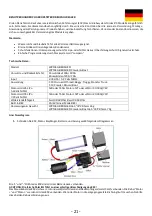
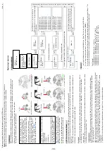
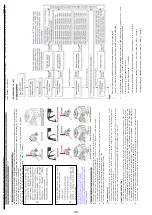
Drück

en

Halten Sie den SET Knopf gedrückt

Eins

chalten

Lass

en Sie den S

et Knopf lo

s

sob

ald die r

ot

e LED blinkt

Neutr

ale P

osition

Vollg

as

Vollbr

ems

e

1s

t Klick

2nd Klick

3r

d Klick

Grüne LED blinkt einmal

Grüne LED blinkt 

zw

eimal

Grüne LED blinkt dr

eimal

Seite

Re

gler pr

ogr

ammier

en

1. 

Pr

ogr

amm Methode

Re

gler aus

Ferns

teuerung an

Drück

en und Halten S

ie 

den S

et Knopf

, R

egler

eins

chalt

en

Ro

te LED blinkt

Grüne LED blinkt

einmal

Set Knopf 3 S

ekunden drück

en

Set Knopf

lo

slass

en

Modus 1 

„F

ahrmodus

Set Knopf

drück

en

Ro

te LED blinkt 1x „

Vor

w

är

ts mit Br

ems

e

Ro

te LED blinkt 2x f

ür “

Vor

w

är

ts

/R

ückw

är

ts

mit Br

ems

e

Grüne LED blinkt

zw

eimal

Set Knopf

lo

slass

en

Modus 2

„Dr

ag Br

ak

e“

Set Knopf

drück

en

Ro

te LED blinkt 1x „0%“

Ro

te LED blinkt 2x „5%“

Ro

te LED blinkt 3x „10%“

Ro

te LED blinkt 4x „15%“

Ro

te LED blinkt 5x „20%“

Ro

te LED blinkt 6x „25%“

Ro

te LED blinkt 7x „30%“

Ro

te LED blinkt 8x „40%“

Set Knopf 3 S

ekunden drück

en

Grüne LED blinkt

dr

eimal

Set Knopf

lo

slass

en

Modus 3

„Abs

chalt

sp

annung

Set Knopf

drück

en

Ro

te LED blinkt 1x „None

Ro

te LED blinkt 2x „2.6V

Ro

te LDE blinkt 3x „2.8V

Ro

te LED blinkt 4x „3.0V

Ro

te LED blinkt 5x „3.2V

Ro

te LED blinkt 6x „3.4V

Set Knopf 3 S

ekunden drück

en

Für die f

olgenden S

chritt

e is

t die s

elbe V

or

gehensw

eis

e wie oben

Set Knopf 3 S

ekunden drück

en

Grüne LED blinkt

x mal

Set Knopf 

lo

slass

en

Modus X

Set Knopf 

drück

en

Drück

en S

ie den S

et Knopf um den W

er

t zu w

ählen

Die An

zahl der r

ot blink

enden LED bedeutet w

elcher

W

er

t ge

w

ählt is

t. (1x is

t W

er

t 1 / 2x is

t W

er

t 2 und s

o

w

eiter)

 .

n

i

e


r

e

d

e

i

w


n

n

a

d


d

n

u


s

u

a


r

e

l

g

e

R


n

e

d


e

i

S


n

e

t

l

a

h

c

S

 .

n

e

s

s

o

l

h

c

s

e

g

b

a


g

n

u

r

e

i

m

m

a

r

g

o

r

P

B

eacht

e:

Im P

rogr

ammierung

spr

oz

ess gib

t der Mo

tor ein „B

eep

“ T

on v

on sich w

enn die LED blinkt

Der 5t

Pr

ogr

ammpunkt wir

d dur

ch 5 kurz

e B

eep T

öne be

schrieben (“BBBBB“). 

Für die ein

zus

tellenden W

er

te jede

s P

rogr

amms wur

de eine länger

e Blinkphas

e und einen langen „B

eep

---“ T

on 

pr

ogr

ammier

t um den W

er

t 5 zu erk

ennen

. Das erleicht

er

t das erk

ennen der höher

en Nmmern

Zum B

eispiel:

„L

ange Blinkphas

e“ (Mo

tor T

on „B---“) = W

er

t 5

„L

ange Blinkphas

e + kurz

e Blinkphas

e“ (Mo

tor T

on „B---B“) = W

er

t 6

„L

ange Blinkphas

e + 2 kurz

e Blinkphas

en

“ (Mo

tor T

on „B---BB“) = W

er

t 7

„L

ange Blinkphas

e + 3 kurz

e Blinkphas

en

“ Mo

tor T

on „B---BBB“) = W

er

t 8

- 34 -

Содержание ADB 1.4

Страница 1: ...1 10 SCALE 4WD ELECTRIC DESERT BUGGY BENDIENUNGSANLEITUNG MANUAL mode d emploi ...

Страница 2: ... 1 ...

Страница 3: ... 2 ...

Страница 4: ... 3 ...

Страница 5: ... 4 ...

Страница 6: ... 5 ...

Страница 7: ... 6 ...

Страница 8: ... 7 ...

Страница 9: ... 8 ...

Страница 10: ... 9 ...

Страница 11: ... 10 ...

Страница 12: ... 11 ...

Страница 13: ... 12 ...

Страница 14: ... 13 ...

Страница 15: ... 14 ...

Страница 16: ... 15 ...

Страница 17: ... 16 ...

Страница 18: ... la Direction 13 AN AUS Schalter ON OFF Switch Intèrrupteur On Off 14 Gas Trimmung Throttle Trimm Trimm des Gaz frein 4 3 2 1 Sender Anleitung Transmitter Manual Mode D emploi 10 4 x AA Alkaling Batteries Open battery cover at the bottom of transmitter Install batteries Follow the direction of batteries designated in the inside of battery box Transmitter Battery Installation Sender Batterie Instal...

Страница 19: ...tching status 4 Press and hold the BIND button on transmitter and switch on the power supply 5 Observe the LED on the receiver if the LED stops flashing the binding process is successful This process takes up to 5 sec 6 Release the BIND button on the transmitter take out the BIND matching line 7 Install the servo for testing 8 If the test fail please repeat the action above 9 If the tests succeeds...

Страница 20: ...d go to brake modus automatically 5 In case can be complete step by step with the above action means setting is correct FAIL SAFE SETUP Failsafe Funktion digitaler Schutz gegen Funkstörungen Die Sicherheitselektronik erkennt wenn falsche zu Funkstörungen mit der Umgebung kommt oder wenn sich das Modell außerhalb der Reichweite des Modell bleibt stehen Setup 1 Den Sender einschalten 2 Empfänger an ...

Страница 21: ...y Ball differential Grease Molybdenum Grease Hex Wrench KNIFE EDGE REAMER Wire Cutters Sharp Hobby Knife Round edge sccissors Sander Benötigte Werkzeuge oder Reifenkleber Benötigte Werkzeuge Tools required Outils nécessaires Outils nécessaires Pince à bec effilé lubrifiant Vernis de blocage des vis Superglue ou colle à pneus clé Allen Graisse différentielle à billes Graisse de molybdam Clé en croi...

Страница 22: ...ahrt Vorwärtslauf 40A 180A Rückwärtslauf 20A 90A Input 2 3S LiPo 5 9 Cells NiMH Anwendung 1 10 On road Off road Buggy Truggy Monster Truck 1 10 Crawler Panzer Boot Motor Limit 2S LiPo 5 6Cells NiMH 540 oder 550er Motor 12T oder u Min 30 000 7 2V Motor Limit 3S LiPo 7 9Cells NiMH 540 oder 550er Motor 18T oder u Min 20 000 7 2V Widerstandsfähigkeit Fwd 0 002 Ohm Bwd 0 004 Ohm Built in BEC 2A 6V Line...

Страница 23: ...ren kann Wenn das ESC betriebsbereit ist ertönt ein langer Piepton Hinweis Bitte kalibrieren Sie den Gasbereich erneut wenn Sie einen neuen Sender verwenden oder die Einstellungen der Neutralstellung von Gaskanal D R ATV ATL oder EPA Parametern ändern da sonst der ESC möglicherweise nicht ordnungsgemäß funktioniert Piepton und LED Status Die Bedeutung des Pieptons LED Status 1 kurzer Piepton NiMH ...

Страница 24: ...igen dass der Ü berhitzungsschutz aktiviert wurde Wenn der ESC auf 80 Grad Celsius abkühlt wird die Ausgangsleistung in den Normalzustand zurückgesetzt 3 Signalverlustschutz Der ESC schaltet die Ausgangsleistung ab wenn das Signal für 0 1 Sekunde unterbrochen wurde Es wird dringend empfohlen die Funktion Failsafe der Funkanlage zu aktivieren Der Unterschied zwischen BRUSHED und BRUSHED CRAWLER BOA...

Страница 25: ... Vollgas Einige Einstellungen im Sender sind falsch Ü berprüfen Sie die Einstellungen Stellen Sie D R EPA ATL auf 100 oder drehen Sie die Regler auf den Maximalwert Stellen Sie TRIM auf 0 oder drehen Sie den Knopf in die neutrale Position Der Motor bricht bei schneller Beschleunigung ein Der Akku hat eine begrenzte Entladefähigkeit C Rate Etwas stimmt nicht mit dem Antriebssystem des Autos Verwend...

Страница 26: ...ted for any damages losses or costs resulting from the use of the product Specification Model WP1040 BRUSHED WP1040 BRUSHED Crawler Boat Cont Burst Current Forward 40A 180A Reverse 20A 90A Input 2 3S LiPo 5 9 Cells NiMH Cars Application 1 10 On road Off road Buggy Truggy Monster Truck 1 10 Crawler Tank Boat Motor Limit 2S LiPo 5 6Cells NiMH 540 or 550 size motor 12T or RPM 30 000 7 2V Motor Limit ...

Страница 27: ...nds to let the ESC execute self test and automatic throttle calibration When the ESC is ready to run a long beep sound is emitted from the motor Note Please calibrate the throttle range again when using a new transmitter or changing the settings of the neutral position of throttle channel D R ATV ATL or EPA parameters otherwise the ESC may not work properly Beep Sound and LED Status The meaning of...

Страница 28: ...inks to indicate the over heat protection has been activated If the ESC cools down to 80 Celsius degree 176 Fahrenheit degree the output power is recovered to normal state 3 Throttle signal loss protection The ESC will cut off the output power if the throttle signal has been lost for 0 1 second The fail safe function of the radio system is strongly recommended to be activated The difference betwee...

Страница 29: ...incorrect Check the settings Set D R EPA ATL to 100 or turn the knobs to maximum value Set TRIM to 0 or turn the knob to its neutral position Motor is cogging when accelerated quickly The battery has limited discharge ability The battery has limited discharge ability Something wrong in the driving system of the car Use battery with better discharge ability Use motor with lower RPM or use smaller p...

Страница 30: ...plication ou la maintenance correcte de nos produits aucune responsabilité ne sera assumée ni acceptée pour les dommages pertes ou coûts résultant de l utilisation du produit spécification modèle WP1040 BROSSÉ WP1040 BROSSÉ Crawler Bateau Suite Courant de rafale Avant 40A 180A Inverse 20A 90A entrée 2 3S LiPo 5 9 cellules NiMH Application de voitures 1 10 Sur route Hors route Buggy Truggy Monster ...

Страница 31: ...t et l étalonnage automatique de l accélérateur Lorsque l ESC est prêt à fonctionner un bip long est émis par le moteur Remarque Veuillez étalonner à nouveau la plage de manettes des gaz lorsque vous utilisez un nouvel émetteur ou modifiez les paramètres de la position neutre du canal de l accélérateur des paramètres D R ATV ATL ou EPA sinon l ESC peut ne pas fonctionner correctement Bip sonore et...

Страница 32: ...tion contre la surchauffe a été activée Si l ESC refroidit à 80 degrés Celsius 176 degrés Fahrenheit la puissance de sortie est rétablie à l état normal 3 Protection contre la perte de signal d accélérateur L ESC coupera la puissance de sortie si le signal d accélérateur a été perdu pendant 0 1 seconde Il est fortement recommandé d activer la fonction de sécurité intégrée du système radio La diffé...

Страница 33: ...s l émetteur sont incorrects Vérifiez les paramètres Réglez D R EPA ATL à 100 ou tournez les boutons à la valeur maximale Réglez TRIM sur 0 ou tournez le bouton à sa position neutre Le moteur roue à la vitesse accélérée rapidement La batterie a une capacité de décharge limitée La batterie a une capacité de décharge limitée Quelque chose ne va pas dans le système de conduite de la voiture Utilisez ...

Страница 34: ...n mit 4 Einstellungen der maximalen Bremsfunktion 8 Einstellungen um die Drag Brake einzustellen 6 4 Start Modis Punch von Soft zu sehr aggressiv um das Anfahren zu verändern 7 Mehrere Sicherheits Features Abschaltung für LiPo s oder NiMH Akkus Überhitzungsschutz Signalverlust Schutz Motor Blockierschutz 8 Einfach einzustellen über den SET Knopf am EIN AUS Schalter Ampere Peak Ampere Widerstand Pa...

Страница 35: ...et werden kann wenn jede Zelle des LiPo s weniger wie 3 5V hat NiMH Akkus Wenn die Spannung des gesamten Akkus höher ist als 9V aber niedriger als 12V wird der Akku als 3S LiPo erkannt Wenn die Spannung weniger als 9V beträgt wird der Akku als 2S LiPo erkannt Zum Beispiel wenn der Akku 8V hat und die Grenze ist bei 2 6V Zelle ist wird der Akku als ein 2S LiPo erkannt Die Grenze bei NiMH Akkus betr...

Страница 36: ...rbindungen Nach einschalten Motor geht nicht an aber ein Warnton beep beep beep beep ertönt 1 Sekunde zwischen beep beep Eingangsspannung ist abnormal zu hoch oder zu gering Überprüfen Sie die Spannung vom Akku Nach einschalten Motor geht nicht an aber ein Warnton beep beep beep ertönt Jedes beep hat einen 2 Sekunden interval Die rote LED leuchtet solide Gassignal ist abnormal Überprüfen Sie die F...

Страница 37: ...cked protection 8 Easily programmed with the SET button on the ESC SPECIFICATIONS Note1 1 The cooling fan on the WP 10BL50 RTR is powered by the built in BEC so the 5V fan is OK and there is no need to consider if the input voltage is high or low 2 In addition please detach the fan from the ESC when running the vehicle in water rain BEGIN TO USE THE NEW ESC 1 Connect the ESC motor receiver battery...

Страница 38: ...ery pack is lower than the threshold for 2 seconds the ESC will cut off the output power Please note that the ESC cannot be restarted if the voltage of each Lipo cell is lower than 3 5V For NiMH battery packs if the voltage of the whole NiMH battery pack is higher than 9 0V but lower than 12V it will be considered as a 3S Lipo If it is lower than 9 0V it will be considered as a 2S Lipo For example...

Страница 39: ...t correct Check the power connections Replace the connectors After power on motor work but emits beep beep beep beep alert tone Every beep beep has a time interval of 1 second Input voltage is abnormal too high or too low Check the voltage of the battery pack After power on motor work but emits beep beep beep alert tone Every beep has a time interval of about 2 seconds And the red LED solid lights...

Страница 40: ...ontrôle sur l utilisation l installation l application ou la maintenance correcte de nos produits aucune responsabilité ne sera assumée ou acceptée pour tout dommage perte ou coût résultant de l utilisation du produit Note 1 1 Le ventilateur de refroidissement sur le WP 10BL50 RTR est alimenté par le BEC intégré de sorte que le ventilateur 5V est OK et il n est pas nécessaire de considérer si la t...

Страница 41: ...ue tonalité bip bip 2 Signal d accélérateur tonalité d alerte anormale Lorsque l ESC ne peut pas détecter le signal d accélérateur normal une telle tonalité d alerte sera émise bip bip bip Il y a un intervalle de temps de 2 secondes entre chaque tonne bip e FONCTIONDE PROTECTION 1 Protection contre la coupure basse tension Si la tension d une batterie Lipo est inférieure au seuil pendant 2 seconde...

Страница 42: ...maintenez la touche SET enfoncée pendant plus de 3 secondes la LED rouge et la LED verte clignoteront en même temps ce qui signifie que chaque élément programmable a été réinitialisé à sa valeur par défaut Il doit être redémarré pour terminer l ensemble du processus DÉPANNAGE problème Raison possible solution Après la mise sous tension le moteur ne peut plus fonctionner aucun son n est émis Les co...

Страница 43: ... 42 ...

Страница 44: ...836 BL version Red 1230865 1230847 1230893 1230893 1230893 1230827 Metallic Red 1230828 Orange 1230829 Green 1230838 1230826 1230894 1230894 1230894 1230889 1230826 1230825 1230825 1230894 1230894 1230826 1230826 1230838 1230894 1230826 1230893 1230853 BD version 1230814 1230913 1230816 1230861 1230901 1230850 1230885 BL version 1230817 1230909 1230898 1230819 BL version 1230821 BD version 1230806...

Страница 45: ...806 BL version 1230878 1230824 1230818 1230827 Metallic Red 1230828 Orange 1230829 Green 1230837 1230834 Green 1230835 Orange 1230836 Red 1230834 Green 1230835 Orange 1230836 Red 1230834 Green 1230835 Orange 1230836 Red 1230909 1230869 1230869 1230860 1230860 1230860 1230906 1230815 1230815 1230894 1230894 1230860 2100004 BD version 2110007 BL version 2020001 2030003 BD version 2030004 BL version ...

Страница 46: ...ff Alu Pinion Gear 10T 2 for Brushless version Gear box Outdrive F Gear box plastic out cover Set Suspension Arm Hing Pin Brace F R Hinge Pin 3 30 4 Front suspension arm set 2 Rear suspension arm set 2 Universal Drive Shaft 2 Steering Knuckle 2 C Hubs 2 Wheel hex nuts 4 Rear Hubs set 2 Rear hub outdrive shaft 2 Drive shafts 2 Front Sway Bar set Rear Sway Bar set Lower Suspension Pins F R Front upp...

Страница 47: ... arm Plastic steering connecting plate Steering Servo Turnbuckle Plastic Plastic servo horn Upper chassis plate Alu Front shock Tower Alu rear shock Tower Alu Front Damper set 2 for brushless version Alu Rear Damper set 2 for brushless version Front Damper set 2 Rear Damper set 2 Front Damper Springs 2 Rear Damper Springs 2 Front shock shaft 2 Rear shock shaft 2 Damper plastic spare part set Serve...

Страница 48: ...ires Set Orange 2 Wheels Tires Set Red 2 Socket Cap Screw M2 10 Flat Head Self tapping Scew M3 8 Flat Head Seif tapping Screw M3 10 Flat Head Self tapping Screw M3 12 Flat Head Self tapping Screw M3 20 Flat Head Screw Set M3 10 Pan Self tapping Screw Set M3 6 Pan Self tapping Screw Set M3 10 Pan Self tapping Screw Set M3 12 Pan Self tapping Screw Set M3 14 Pan Self tapping Screw Set M3 16 Pan Self...

Страница 49: ... φ8 φ3 2 0 5 Washers φ7 5 φ5 1 2 1 Differential seal Asbestos paper friction plate φ25 5 17 5 1 0 Bearing set for all size Screw set for all size Alumimium Steering cup C mounts Alumimium Rear Hub Alumimium Steering Slider Brushed Motor Brushed Speed Controller 6kg PG servo for BD version Upgrade Part List Tuningteile More add on and tuning parts you will find at Mehr Anbau und Tuningteile finden ...

Страница 50: ...Absima GmbH Gibitzenhofstr 127a RG 90443 Nürnberg Germany Web www absima com ...

Отзывы: