Abov E-GANG4 - Идеальный компаньон для вашей электроники. Получите полное руководство по использованию в формате PDF бесплатно. Скачайте инструкцию пользователя с manualshive.com прямо сейчас и наслаждайтесь всеми функциями продукта без проблем.
List of Figures
E-PGM+ / E-GANG4/6 / E-PGM Serial User’s Manual
4
Figure 49. Example of Multiple Connections of E-PGM+ ..................................................................... 43
Figure 50. Internal Step-up Power Selection ........................................................................................ 44
Figure 51. Insertion of 200 Ohms in VPP Line ...................................................................................... 45
Страница 1: ...Global Top Smart MCU Innovator ABOV Semiconductor www abovsemi com E PGM E GANG4 6 E PGM Serial Programmer User s Manual Version 1 0 3...
Страница 2: ...tware UI Descriptions 22 3 4 Device Selection 33 3 5 Programmer Self Check 35 3 6 Programming Error Messages 37 3 7 Troubleshooting 38 3 7 1 Error Message The program can t start because WDAPI1010 dll...
Страница 3: ...0 Software Version Information 22 Figure 21 Select Hex File Type 23 Figure 22 Save HPO 23 Figure 23 Displayed Progress Bar 24 Figure 24 Example Options of A96T418 24 Figure 25 Device Password 25 Figur...
Страница 4: ...of Figures E PGM E GANG4 6 E PGM Serial User s Manual 4 Figure 49 Example of Multiple Connections of E PGM 43 Figure 50 Internal Step up Power Selection 44 Figure 51 Insertion of 200 Ohms in VPP Line...
Страница 5: ...List of Tables 5 List of Tables Table 1 Programmer Specifications 7 Table 2 Programmer Functions 7 Table 3 Pin Assignment for 40 pin TEXTOOL Socket 15 Table 4 Connection Table for 10 pin IDC Connecto...
Страница 6: ...USB 2 0 Full Speed interface with Microsoft Windows Built in protection circuit for the Programmer and programmed device Data port inputs are protected against ESD up to 15kV Supports single chip pro...
Страница 7: ...X 4 3 48 2 X 23 X 4 3 Weight g 350 330 2 000 2 800 Power Source External DC 15V Power Supply Input Voltage 15V 1A 15V 1A 15V 2A 15V 2A Power Consumption 15W 15W 30W 30W Operating Temp 10 40 Storage Te...
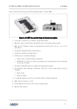
Страница 8: ...R button and joystick buttons are individually replaceable ensuring a long service life Functions of the E PGM E GANG4 6 and E PGM Serial are described in the following sections 2 2 1 E PGM Programmer...
Страница 9: ...tton for programming the target device A button for reading the target device LCD Screen for Information Display Device name checksum data and options PASS FAIL is shown as a result of programming acc...
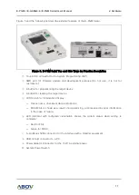
Страница 10: ...type universal Programmer which is capable of programming any series of ABOV s Flash microcontrollers 94 95 96 97XXXX series except for 97F1104S 1204S 1316S and all 32 bit MCUs The E PGM Serial is us...
Страница 11: ...tton for programming the target device A button for reading the target device LCD Screen for Information Display Device name checksum data and options PASS FAIL is shown as a result of programming acc...
Страница 12: ...ng Programmers which are capable of programming any series of ABOV s microcontrollers with a gang mode that allows multiple devices to be programmed simultaneously The E GANG4 and E GANG6 consist of f...
Страница 13: ...D port for firmware update and development purpose Not for use A button for programming the target device G1 only A button for reading the target device LCD Screen for Information Display Device name...
Страница 14: ...en writing is complete Red for FAIL Green for PASS A button for the simultaneous programming for all the four or six gangs System Power Switch of E GANG4 6 This connector is for the 15V 2A power adapt...
Страница 15: ...L socket of the E PGM or E GANG4 6 before conducting programming We provide all sockets and adaptors which are supported by the E PGM and E GANG4 6 Please refer to the Socket and Adaptor Selection Gui...
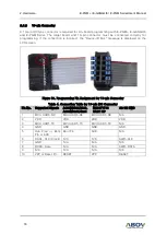
Страница 16: ...s displayed on the LCD screen Figure 10 Programming Pin Assignment for 10 pin Connector Table 4 Connection Table for 10 pin IDC Connector Pin No Supported Signals AC33M6128 8128 AC33M3064 4064 MC80F77...
Страница 17: ...sted by us and the certified version of program is uploaded to our website Additional software updates are provided through the special version development process upon requests by customers For more...
Страница 18: ...o the Development Tools Programmer E PGM E Gang4 6 E PGM Serial menu 2 Download the E PGM E GANG4 6 USB Driver for 32 64 bit OS and the E PGM E Gang Software shown in Figure 11 Figure 11 Software Down...
Страница 19: ...After executing the exe file the window shown in Figure 14 appears if the installation is successful The installation takes one to three minutes depending on the PC environment Figure 14 Driver Instal...
Страница 20: ...The E PGM or E GANG4 6 should be automatically recognized and displayed in Device Manager as shown in Figure 15 Figure 15 Device Manager 9 Unzip the E PGM E GANG4 6 E PGM Serial Software that was down...
Страница 21: ...d with a pop up shown in Figure 17 right click on the file for the context menu Figure 17 Windows Warning Message 11 Select the Properties and click the Unblock under Security Then double click the ex...
Страница 22: ...ection software functions are introduced 1 Figure 19 E PGM PC Program The Ver Info button displays the software version If the Ver Info button is pressed a dialog box pops up to show the software vers...
Страница 23: ...ormat suited for the device Make sure everything is correct then click OK to proceed Figure 21 Select Hex File Type a The Load HPO button is used to load an already existing HPO file The HPO file is a...
Страница 24: ...is displayed next to the progress bar as OK or Fail upon completion a E PGM E PGM Serial b E GANG6 Figure 23 Displayed Progress Bar The Device Option button is used to check or modify option values o...
Страница 25: ...Password The Address Range shows the start and end addresses of ROM when a device is selected These values are fixed and cannot be modified by users This area displays the checksum When a hex file is...
Страница 26: ...desired device Figure 26 Device Select When a device is successfully selected in the previous step using the Device Select button the device name is displayed in text form When the E PGM E PGM Serial...
Страница 27: ...running the software without the E PGM and E GANG4 6 connections If the Save HPO button is clicked two options such as E PGM and E PGM Serial are available Figure 28 Choose Type After selecting the c...
Страница 28: ...tage of RESET IC on board must be lower than VDD of E PGM Example If the reset voltage is 4 2V and Set VDD is 3 3V programming may be failed because the device of board is on reset The LVR voltage of...
Страница 29: ...Data Flash If users select the Erase Data Flash in Figure 31 the Data Flash is erased during write sequence Supported devices are A33G527 and A33G526 Figure 31 Tool Options Erase Data Flash The Tool O...
Страница 30: ...rs can set the options of the Config Serial ID Figure 33 Options of Config Serial ID a Start addr Start address of serial ID b Length Length of serial id 4 byte or 8 byte c Value ID value d Little end...
Страница 31: ...ool Options button also enables the Set Limit Number of Write Figure 34 Tool Options Config Limit Number of Write Figure 35 Write Counter a Enable the Limit Number of Write b Enter the available write...
Страница 32: ...E PGM E GANG4 6 E PGM Serial User s Manual 32 The Log dialog shows the progress and results in real time Users can check the problems and solutions that occurred before progress recording Figure 36 L...
Страница 33: ...and E Gang 6 The number of ports is displayed in the GUI when any of the products is connected 1 port for E PGM and E PGM Serial 4 ports for E GANG4 6 ports for E GANG6 Figure 37 Port Selection To pre...
Страница 34: ...pops up the option dialog box Refer to the device s manual and select the appropriate options according to application characteristics Click the Update button to update the E PGM or E GANG4 6 with th...
Страница 35: ...elf Check For this users need to follow the procedure below 1 Remove a device in a tool 2 Run the E PGM exe file 3 Device select SELF_TEST E PGM 4 Press the Update button 5 Run TEST after the update i...
Страница 36: ...6 E PGM Serial User s Manual 36 Figure 40 Button of Programmers The Self Check results are displayed on the Programmer s LCD screen Figure 41 shows example results on the LCD screen a Pass c Fail Figu...
Страница 37: ...nd causes a voltage drop or during on board programming the target board is short between VDD and GND Trim Chk Failed No device specific data is found or during on board programming the device is rese...
Страница 38: ...is not found in the C Windows folder Solution If the device driver has been set up the missing file can be copied into the C Windows folder 3 7 2 Error Message No firmware found or Device file not fo...
Страница 39: ...USB line 3 Run the USB_driver_unistall exe file version 1 7 4 Delete the windrvr6 sys file that is located in the directory C Windows System32 drivers 5 Copy the windrvr6 sys file from the driver ins...
Страница 40: ...s all those devices are programmed simultaneously The hardware description for the handler connection is provided in the following sections 4 1 E PGM E PGM Serial Handler Connections The software and...
Страница 41: ...OD FAIL Output pin active low indicate signals 1 Marking 1 2 3 4 5 6 7 8 9 10 11 12 Pin No Marking Name 1 Blank Not used 2 F4 FAIL4 3 G4 GOOD4 4 T_5V Target Power 5 START START 6 T_GND Target GND 7 F3...
Страница 42: ...dicate signals 1 1 Marking 1 2 3 4 5 6 7 8 9 10 11 12 Pin No Marking Name 1 F6 FAIL6 2 G6 GOOD6 3 F5 FAIL5 4 G5 GOOD5 5 F4 FAIL4 6 G4 GOOD4 7 T_5V Target Power 8 START START 9 T_GND Target GND 10 F3 F...
Страница 43: ...can connect multiple E PGM units between Start and GND pins respectively as shown in Figure 49 With this configuration the button inputs on any single Programmer are delivered to all the connected uni...
Страница 44: ...et the SW3 switch in the Step up position to ensure a maximum VPP level of 19V When programming any other devices on the other hand users must set the switch to be in the Ext position to limit the max...
Страница 45: ...other signals affect communication in ISP mode disconnect them from the pins DSDA DSCL using a jumper or switch 2 A 200 resistor must be installed at the target board Without it an MCU can be damaged...
Страница 46: ...Revision History E PGM E GANG4 6 E PGM Serial User s Manual 46 Revision History Version Date Description 1 0 3 Mar 12 2021 First released...
Страница 47: ...anties and shall not be responsible or liable for any injuries or damages related to use of ABOV products in such unauthorized applications ABOV and the ABOV logo are trademarks of ABOV All other prod...