background image

32-bit MCU Current Sensing Board Design Guide


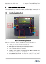
5. Quick Start Guide: Setup and Use


19 

5.2


Example Firmware Project Compiling and Downloading 

In this section, users can learn a method to compile, debug, and download an example firmware project. 


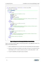
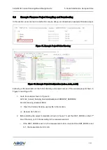
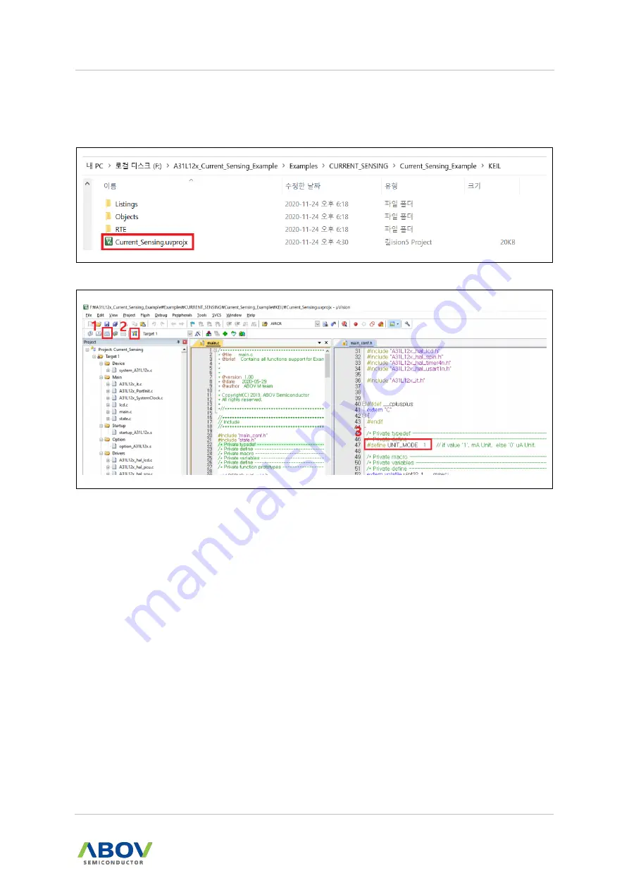
Figure 14. Example Project Folder Directory 


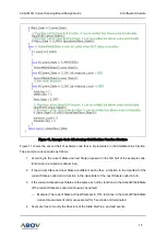
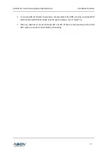
Figure 15. Example Project Configuration (main.c, main_conf.h) 

Following is the description of the folder directory and project menus of the example project shown in 
Figure 14 and Figure 15: 

1.


Go to the location shown in Figure 14: 
A31L12x_Current_Sensing_Example\Examples\CURRENT_SENSING\ 
Current_Sensing_Example\KEIL\ 


Open the Current_Sensing.uvprojx file in the location. 


Execute Keil uVision. 

2.


Before starting the project compilation shown in Figure 15, set the UNIT_MODE on the 47

th


line of the main_conf.h file according to the measurement unit. 


If the UNIT_MODE is set to 0, the measurement unit is uA while if the UNIT_MODE is set 
to 1, the measurement unit is mA. 


Содержание A31L12X

Страница 1: ...Global Top Smart MCU Innovator ABOV Semiconductor www abovsemi com A31L12X Current Sensing Board Design Guide using Low Power MCU Application Note Version 1 00...

Страница 2: ...iagram 4 Figure 2 Current Sense Amplifier INA190 Block Diagram 5 Figure 3 Current Sense Amplifier Circuit Layout Example 7 Figure 4 24 bit ADC LTC2400 Block Diagram 8 Figure 5 Internal SCK SPI Comm Op...

Страница 3: ...a Low Power MCU A31L12X reduces the operating current by utilizing DEEP SLEEP mode During DEEP SLEEP mode it consumes about 1uA with 3V power source For detailed information of A31L12X specification p...

Страница 4: ...ing Board Block Diagram 32 bit MCU Current Sensing Board Design Guide 4 2 Current Sensing Board Block Diagram Figure 1 shows a functional block diagram of the Current Sensing Board Figure 1 Functional...

Страница 5: ...uming low power For detailed information of this part please refer to INA190 Technical Document Figure 2 Current Sense Amplifier INA190 Block Diagram Figure 2 shows a basic circuit configuration of th...

Страница 6: ...5W 3 3V GAIN 500 the resistor value of Rsense is calculated as 66 As a result the Current Sensing Board for uA measurement uses a resistor of 50 If users determine the range of the current to measure...

Страница 7: ...be placed close to the power and ground pin of the INA190 The value of the bypass capacitor is recommended as 0 1uF The impedance generated in the wiring is minimized when the connection length betwee...

Страница 8: ...e 4 24 bit ADC LTC2400 Block Diagram Figure 4 shows a basic circuit configuration of the 24 bit ADC Users who use this part for circuit designs and software SPI communication configuration need to con...

Страница 9: ...SCK the SCK of the LTC2400 is digital output and the MCU A31L12X becomes Slave to receive the SCK as its Input When using the internal SCK the SDO of the LTC2400 is digital output and the MCU A31L12X...

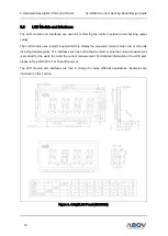
Страница 10: ...LCD to display the measured current value in uA or mA units including decimal points The interfaces such as button that can start or stop the current measurement is provided for the users to control t...

Страница 11: ...y using LCD driver peripherals of A31L12X 2 The GDC8310 operates with 3 3V of operation voltage and uses 1 4 Duty 1 3 Bias drive techniques 3 Each of COM and SEG of A31L12X and GDC8310 can be connecte...

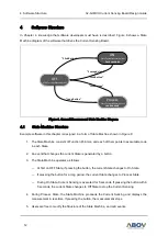
Страница 12: ...hown in Figure 8 1 The State Machine consists of Function Pointers and each of them points to executable code in each State 2 An event that changes the current State is generated by a button 3 The Sta...

Страница 13: ...es functions executed when the current State changes entering new State due to the event occurrence such as button pressing 2 ActionWhileInState S_MAX includes functions executed after the UponEnter f...

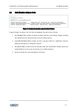
Страница 14: ...ented in the StateMachine function The example code operates as follows 1 When the StateMachine function is called the event and current State is stored as parameters 2 During the current State next S...

Страница 15: ...are determined 2 If the current State and next State are different each other a function in the UponExit of the current State is called and a function in the UponEnter of the next State is called in...

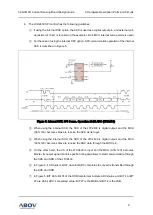
Страница 16: ...munication Software Code Figure 12 shows an example software code that intends to communicate with the 24 bit ADC shown in Figure 5 Figure 12 24 bit ADC LTC2400 SPI Comm Operation Code and Waveforms 1...

Страница 17: ...ata consecutively the level state of the SDO is read by using the GPIO external interrupt at Positive Edge see the above example code in Figure 12 3 When spi_data fills up the 32 bit length BIT 4 to B...

Страница 18: ...uation Board The hardware on the Current Sensing Evaluation Board shown in Figure 13 is as follows 1 An LCD module and current sensing input terminals N and P 2 A button controlling the start and term...

Страница 19: ...f the folder directory and project menus of the example project shown in Figure 14 and Figure 15 1 Go to the location shown in Figure 14 A31L12x_Current_Sensing_Example Examples CURRENT_SENSING Curren...

Страница 20: ...icon 1 shown in Figure 15 to start compilation 4 When the compilation is completed connect to the debugger terminal on the example board 5 Click on the icon 2 shown in Figure 15 to start firmware dow...

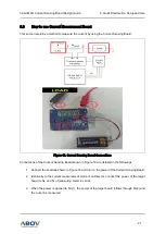
Страница 21: ...onnections Connections of the Current Sensing Board shown in Figure 16 are detailed in the followings 1 Connect the board as shown in Figure 16 and turn on the power of the Current Sensing Board 2 Ide...

Страница 22: ...to start the current measurement If pressing the button for a long period it means to proceed the current measurement continuously If pressing the button for short period it means to terminate the cur...

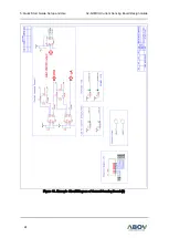
Страница 23: ...k Start Guide Setup and Use 23 5 4 Example Circuit Diagram and Firmware Source for Current Sensing Board Figure 17 and Figure 18 show the example circuit diagrams of the Current Sensing Board Figure 1...

Страница 24: ...5 Quick Start Guide Setup and Use 32 bit MCU Current Sensing Board Design Guide 24 Figure 18 Example Circuit Diagram of Current Sensing Board 2...

Страница 25: ...32 bit MCU Current Sensing Board Design Guide 5 Quick Start Guide Setup and Use 25 By providing the example source on ABOV s website users can open the example firmware and utilize it in actual design...

Страница 26: ...ard Design Guide 26 6 Conclusion This document introduces a method to design hardware and configure software for the current sensing and measurement This document provides actual example board to help...

Страница 27: ...32 bit MCU Current Sensing Board Design Guide 7 References 27 7 References Texas Instrument INA190 Current Sense Amplifier Linear Technology LCT2400 24 bit ADC ABOV Semi A31L12X 32bit MCU...

Страница 28: ...Revision History 32 bit MCU Current Sensing Board Design Guide 28 Revision History Version Date Description 1 00 20 11 30 Initial preliminary version created...

Страница 29: ...ranties and shall not be responsible or liable for any injuries or damages related to use of ABOV products in such unauthorized applications ABOV and the ABOV logo are trademarks of ABOV All other pro...

Отзывы: