32-bit MCU Current Sensing Board Design Guide
3. Hardware Description: Parts and Circuits
11
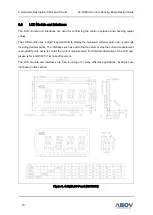
Figure 6 shows a basic circuit configuration of the LCD module. Users who use this part for LCD control
need to consider the followings:
1.
The LCD module in Figure 6 can be controlled by using LCD driver peripherals of A31L12X.
2.
The GDC8310 operates with 3.3V of operation voltage and uses 1/4 Duty 1/3 Bias drive
techniques.
3.
Each of COM and SEG of A31L12X and GDC8310 can be connected by matching them as
shown in Figure 7.
Figure 7. Connections Circuit Diagram of A31L12X and 4-Digit LCD Panel
Finally, a button is added to start or stop the current sensing measurement. For detailed information of
the control method, please refer to example code in

