
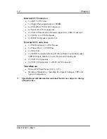

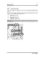
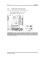
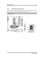
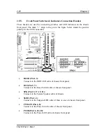

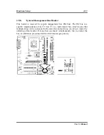
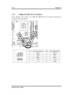
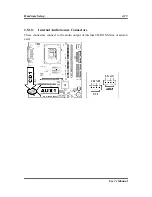


Hardware Setup
2-11
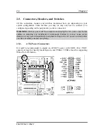
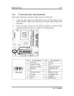
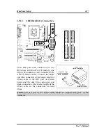
2.5.6.
Front Panel Audio Connection Header
This header provides the connection to audio connector at front panel.
•
To use the audio connector at front panel, remove all the jumpers on this
header, and then connect to front panel by the extension cable provided with
the chassis.
•
To use the audio connector at rear panel, disconnect the extension cable,
attach the jumpers back at pin 5-6, and pin 9-10 (default setting).
Pin
Pin Assignment
Pin
Pin Assignment
1 Audio
Mic.
2 Ground
3
Audio Mic. Bias
4
VCC
5
Speaker Out Right
Channel
6
Speaker Out Right
Channel Return
7 X
8 NC
9
Speaker Out Left
Channel
10
Speaker Out Left
Channel Return
11 Ground
12 S/PDIF
In
13 VCC
14 S/PDIF
Out
User’s Manual
Содержание IS-10 Intel Pentium 4 System Board Socket 478
Страница 1: ...IS 10 IS 11 IS 12 Socket 478 System Board User s Manual 4200 0383 02 Rev 1 00 ...
Страница 5: ...1 1 User s Manual User s Manual ...
Страница 18: ...14 IS 10 IS 11 IS 12 ...
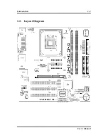
Страница 21: ...Introduction 1 3 1 2 Layout Diagram User s Manual ...