Manual ZX0 HB 600 en - Revision 05 |
17
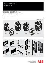
2.2.1 Installation of the standard
foundation
frame
(600 mm)
(965 mm)
front side
c)
rear side
c)
For panels of 600 mm width
d)
For air-insulated metering panels, width 1000 mm
d)
front side
rear side
Standard foundation frames are delivered to site completely pre-
assembled.
Installation principle:
The foundation frames are bolted together at the front and rear.
Vertical alignment is effected by jacking screws. Brackets are
used to fasten the frames to the floor. The foundation frames are
finally embedded in the floor topping to provide their load bearing
capacity.
Detailed description of installation
(Fig. 2.2.2.1)
- Position the foundation frame sections in the correct loca-
tions on the concrete floor.
- Align the foundation frame vertically with the four screws
(1), taking account of any deviation in floor level in the
direction of the foundation frames which are still to be laid.
- Fasten the brackets (2) of the foundation frame to the
floor, using one knock-in anchor (5) and one screw (3) with
dished washer (4) for each bracket.
- Slide a slot rod (6) into the front slot of the front section
and, if the rear sections of the two frames to be connected
are aligned (i.e. have the same depth) a slot rod into the
rear slot of the rear section. Tighten the grub screws in the
slot rods.
- Place the following foundation frame in the correct position
on the floor, allowing the inserted slot rods to slide into the
sections of the frame to be installed. Bolt the foundation
frames together with two M 8 x 100 cheese head screws
(7) and nuts and washers. Tighten the grub screws in the
slot rods.
- Align the foundation frame vertically as described above
and fasten it to the floor.
- Install the following foundation frames in the same way.
(1000 mm)
(890 mm)