IB 6.2.7.7-3I
7
NOTE: If the Release Lever cannot be turned to
the left, make sure breaker is first in the Open
position.
C. The Release Lever cannot be operated when
the breaker is in the closed position. This
prevents connecting or disconnecting the
breaker from the Primary Stabs in the
compartment with the breaker closed. A
Racking Lock Bracket, operated by the
breaker’s Jackshaft, blocks the Index Lever
when the Jackshaft is in the closed position. If
the interlock is not functioning as noted,
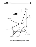
perform the following inspections. Refer to
Figure A6 in the Appendix.
1. Check that the Racking Lock Bracket is
connected to the Jackshaft via a Link. If
not connected then reconnect.
NOTE: The Operations Counter and the
Open/Closed Indicator are also driven by the
same Racking Lock Bracket.
2. Check that nothing in the Racking
Mechanism is bent.
D. When the circuit breaker is between the
WITHDRAW, DISCONNECT, TEST and
CONNECT positions, any attempt to close the
breaker will discharge the Closing Springs
,
and the contacts will not close. This is referred
to as "Trip Free" operation. The finger of the
Index Lever rides on the circumference of the
Rack Screw, holding the Release Lever in its
released position. A linkage between the
Release Lever and Trip Latch then holds the
Trip Latch in its unlatched position. If this
interlock is not functioning as noted, perform
the following:
1. Confirm that the Trip Latches are properly
adjusted and functioning. Position the
Rack Screw so the Rack Mechanism is in
the DISCONNECT, TEST or CONNECT
position. Charge and Close the breaker,
and then press the Manual Trip Button.
NOTE: If the breaker does not trip the Trip
Latch and/or linkage is at fault. Contact
the Customer Service Center for
assistance.
NOTE: When the Racking Mechanism is
between the WITHDRAW, DISCONNECT,
TEST, or CONNECT positions the Manual
Trip Button should have a slight amount of
play so as not to “Bottom Out”. The
Adjustable Link and the Link to Trip Lever
(See Figure A6 in the Appendix) both can be
adjusted to accomplish this. Adjustment is as
follows:
1. If adjustment is necessary, the “Link to
Trip Lever” should be adjusted first to get
the slight play in the Trip Linkage.
2. If necessary, the Adjustable Link can be
adjusted after first removing one of the
securing Retainer Rings.
3. The interlock should now be properly
adjusted. Confirm by retesting the
interlock.
4. If the interlock is now functioning properly,
replace the retainer removed in step 2.
5. If the Adjustable Link setting is changed,
the Padlock Hasp Provision in the
previous section will have to rechecked for
proper operation.
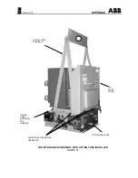
Installing Circuit Breaker Into Compartment
(See Figure A8 in the Appendix)
NOTE: Model 80 breakers do not have Racking
Mechanisms. They are bolted-in units.
NOTE
:
CLOCKWISE rotation of racking crank for
inserting breaker. COUNTERCLOCKWISE
rotation of racking crank for removal of breaker.
1. Turn Motor Disconnect Switch (if so equipped)
to the OFF position. Refer to Figures A3 and
A4 in the Appendix.
NOTE: Step 2 is possible only if Racking
Mechanism is in CONNECT, TEST or
DISCONNECT positions, and the breaker is
Open)
2. Make sure the Racking Mechanism is in the
WITHDRAW position. This can be done by
first turning the Release Lever to the left.
While holding the Release Lever to the left,
engage the Racking Crank (accessory) into


