IB 6.2.7.7-3I
1
5
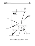
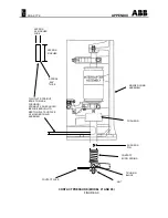
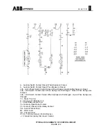
ELECTRICAL CHARACTERISTICS OF
CONTROL DEVICES - (REFER TO
FIGURES A12 AND A13 IN THE
APPENDIX)
NOTE: The charging time of the breaker with the
new Ryobi Motors is approximately four seconds.
For operating voltage ranges and normal current
draw for various nominal control voltages, refer to
Tables A1 and A2 in the Appendix. The current
values given are average steady state values.
Momentary inrush currents for all charging motors
and coils are approximately three times these
values.
Please refer to the specific schematic diagrams
and other operational information furnished with
your order. Typical schematics for general
electrical information can be found in the
Appendix.
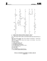
DC and AC Closing Operating Sequence
With the circuit breaker open, closing springs
discharged, control power source energized, and
motor disconnect switch to ON position, operation
occurs as follows:
1. Immediately upon the availability of control
power across disconnects "5" and "02", the
spring charging motor is energized, which in
turn charges the closing springs. When the
closing springs are charged, limit switch
contact "LSb" is opened, and limit switch
contact "LSa" is closed.
2. Operation of the close control switch (with its
power source), connected to disconnects "03"
or "7" and disconnect "6", energizes the latch
release coil (X) through the circuit breaker
auxiliary switch "b" contact, the normally
closed lockout relay contact "Yb", limit switch
contact "LSa". The latch release coil (X)
releases the closing latch. The springs then
discharge to close the circuit breaker.
3. When the springs discharge, limit switch
contacts "LSb" closes and switch contact
"LSa" opens.
4. When limit switch "LSb" in the motor circuit
closes, the spring charging motor is
energized, which in turn recharges the closing
springs.
5. When the circuit breaker closes, all auxiliary
switch "b" contacts open and all auxiliary
switch "a" contacts close.
6. When the limit switch contact "LSb" closes,
the lockout relay coil (Y) is energized and
opens lockout relay contact "Yb", which de-
energizes the latch release coil (X). Lockout
relay contact "Ya" closes, which seals-in the
lockout relay coil (Y) as long as the "close"
contact is maintained. The purpose of the
lockout relay coil (Y) is to prevent pumping of
the closing mechanism when closing against a
faulted circuit.
7. After the breaker has closed and the "close"
switch is released by the operator, the lockout
relay coil (Y) is de-energized. This allows the
normally-closed lockout relay contact "Yb" to
close, and the normally-open lockout relay
contact "Ya" to open.
8. The circuit breaker can be tripped by
operation of the trip control switch, connected
to disconnects "3" or "04" and disconnect "10",
which energizes the circuit breaker trip coil
(TC) through the auxiliary switch "a" contact.
9. The Undervoltage Device, if furnished,
provides a direct acting lock-open and
undervoltage tripping feature. This device
must be energized to initially close the
breaker, and also to maintain the breaker in a
closed position.
10. The latch check switch, if furnished, insures
that the tripping mechanism must be reset
prior to energizing the closing latch release
coil (X).
AC Closing Operating Sequence
(Prior to January 1996)
With the circuit breaker open, the closing springs
uncharged, the control power source energized
across disconnects "5" & "02" and "01" & "6", and
the motor disconnect switch to ON position,
operation occurs as follows:


