11
General
1.0 Technical details
1.1 Type designation
1.2 Specifications
1.3 Rating plate
2.0 Breaker details
3.0 Function
3.1 Switching operations
3.2 Closing operation
3.3 Opening operation
4.0 Installation
General
4.1Preparations
4.2 Installation procedure
4.2.1 Installation of breaker with
cabinet attached to the pole duct
4.2.1.1 Unpacking of structure
4.2.1.2 Various parts of structure
assembly
4.2.1.3 Assembly sequence for
structure
4.2.1.4 Dismantling of cases
4.2.1.4.1 Unpacking of
cabinet
4.2.1.4.2 Unpacking of
duct & Pole
assembly
4.2.1.5 Assembly of duct with poles
on cabinet
4.2.1.6 Assembly of entire circuit
breaker on structure
4.2.2 Installation of breaker with cabinet
at lower height
4.2.2.1 Various parts of structure
assembly
4.2.2.2 Unpacking of structure
4.2.2.3 Assembly sequence for structure
4.2.2.4 Unpacking of duct & pole
assembly
4.2.2.5 Dismantling of cases
4.2.2.5.1 Unpacking of cabinet
4.2.3 High voltage connections
4.2.4 Low voltage connections
4.2.5 Earthing
5.0 Commissioning
5.1 General procedure
5.2 Space heaters
5.3 Starting conditions
5.4 Function test
5.5 Trial switching operations
5.6 Anti-pumping device
5.7 Check of heaters
5.8 Concluding work
6.0 Periodical checks
6.1 General
6.2 Checking programme
6.3 General Inspection of the circuit
breaker
PART B Installation, Operation & Maintenance
Содержание VBF Series
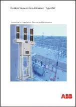
Страница 1: ...Outdoor Vacuum Circuit Breaker Type VBF Instruction for Installation Service and Maintenance ...
Страница 51: ...FIG 3 TYPICAL SCHEMATIC DIAGRAM FOR VBF36 51 Drawings ...
Страница 53: ...53 Drawings Fig 4c View from Rear side Covers removed ...
Страница 58: ...58 Dismantling of Operating Coils Setup Disconnect the motor power supply 7 Fig 11 Fig 12 Motor ...


