22
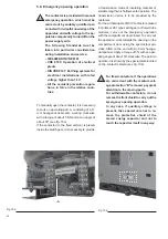
A
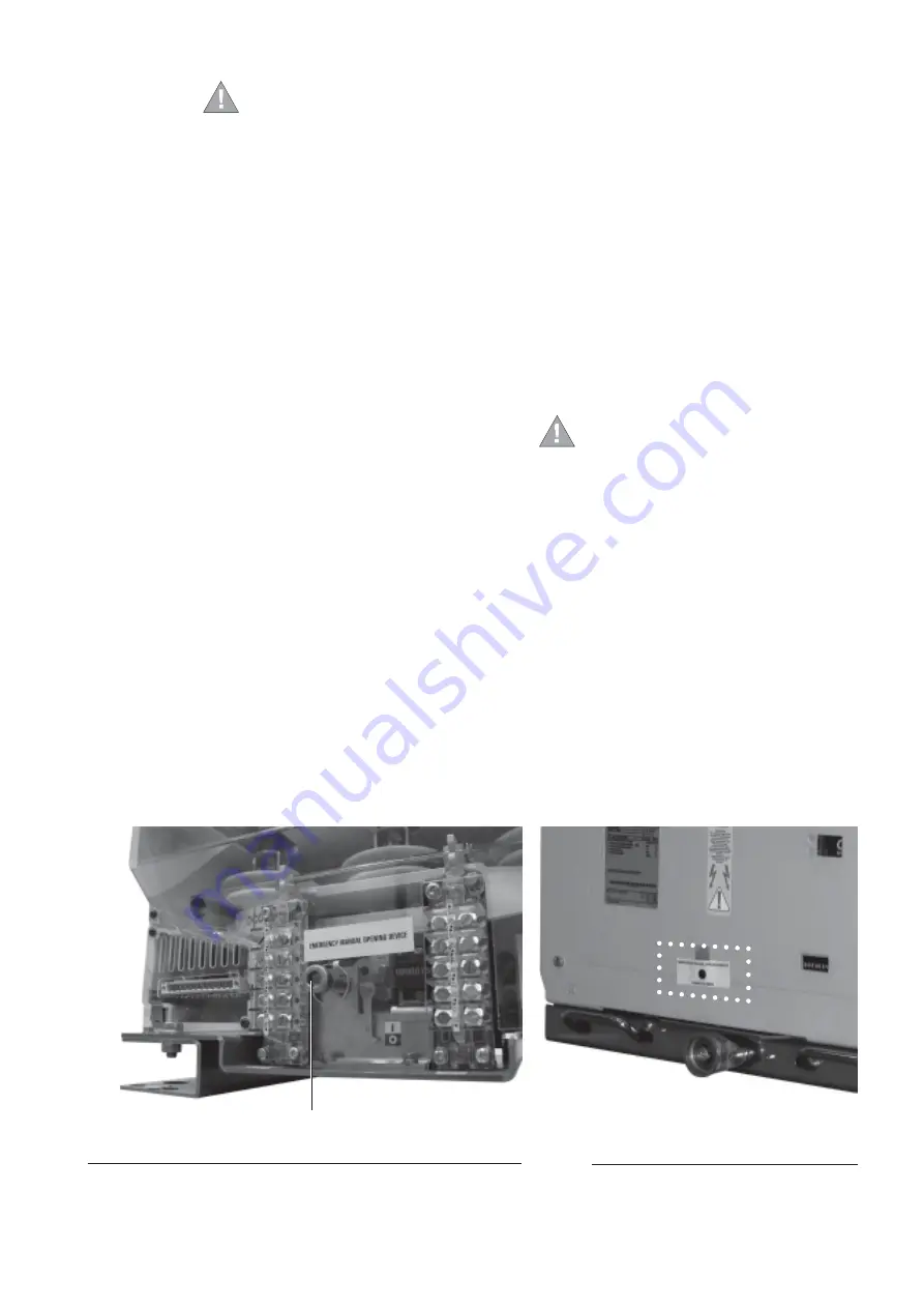
Fig. 10 a
a transmission made of insulating material of
suitable length which allows safe operation. The
transmission device is to be provided by the
customer.
For the withdrawable VSC/P contactors placed
in UniGear ZS1 type switchgear or PowerCube
modules, carry out the emergency operation
with the compartment door closed. To carry out
the operation, work towards the opening on the
compartment door using the special tool pro-
vided, fitted on the end with an 8 mm hexago-
nal spanner. Apply a torque of 5 N with an oper-
ating angle of about 30° clockwise. The point to
operate in is shown by the special plate located
on the contactor shield (see fig. 10b).
For fixed contactors, if the operations
are carried out with the medium volt-
age protection “B” removed, pay great
attention to the moving parts.
For withdrawable contactors, do not
remove the front shield to carry out the
emergency opening operation.
In any case, if auxiliary voltage is
present, take special care not to re-
move the protective shield of the
stored energy capacitor and not to
touch the capacitor itself in any way.
5.8. Emergency opening operation
The contactor is provided with manual
emergency operation which must be
carried out by suitably qualified per-
sonnel with in-depth knowledge of the
apparatus and with voltage to the ap-
paratus compulsorily turned off on the
power supply side.
The following Standards must be
taken into particular consideration
during installation and service:
– IEC60694/DIN VDE 0101
– VDE 0105: Operation of electrical
plants
– DIN VDE 0141: Earthing systems for
electrical installations with rated
voltage higher than 1 kV
– All the accident prevention regula-
tions, in force in the relative coun-
tries.
To manually open the contactor, it is necessary
to work on operating part A, consisting of a 17
mm hexagonal-head bolt, working clockwise
with a torque of about 5 Nm and at an angle of
about 30° (see fig. 10a).
If the contactor (in the fixed version) is placed
inside the switchgear, it is necessary to provide
Fig. 10 b
Содержание V-Contact VSC 12
Страница 1: ...V Contact VSC Installation and service instructions 7 2 12 kV 400 A ...
Страница 2: ...1 ...
Страница 35: ...33 50 50 49 49 Fig 18c Fig 18b ...
Страница 39: ...1 ...

