


50
Installation and commissioning guide UCL/VUCL
|
1ZSC000562-AAZ en
9.2.5 Mounting of horizontal drive shafts for two units
Mount the shaft between the motor-drive mechanism and
unit-1 according to Section 9.2.4.
Mount the shaft between unit-1 and unit-2, as follows:
1. Loosen the set screws for the locking device of the bevel
gear on the top of the tap-changer; see Fig. 42. Remove
the locking device.
2. Mount the cover SA33 and tighten the set screws (from
the locking device).
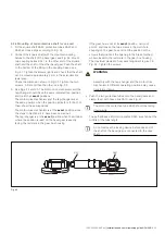
3. Fit the square shaft SA30, protective tubes SA31 and
SA32 and hose clips according to Fig. 41.
4. Connect the square shaft with the mounted coupling
halves to the shaft of the bevel gear; see Fig. 41. Mount
two coupling halves SA11 to the other end of the square
shaft and the shaft of the other bevel gear. Push the shaft
to the bottom of the fitting in the coupling halves; see
Fig. 31. Tighten the screws lightly and check that the shaft
can be moved approximately 2 mm in the axial direction
(axial play). Check the dimension shown in Fig. 30. Tighten
the two screws; A first and then the other; see Fig. 32.
If the exact position of the closest unit has been
adjusted, the locking device might have to be
removed (step 6) before step 3 can be carried out.
5. See Figs. 24 and 25. The motor-drive mechanism and the
tap-changer should have the same indicated tap position
and be at their
exact
positions.
The motor-drive mechanism and the tap-changer are at
the same position when the position indicators for both of
them show the same position.
The motor-drive mechanism is at the
exact
position since
the steps in Section 9.2.2 have been carried out.
The tap-changer is at the
exact
position when the window
where the position is read on the bevel gear is exactly
facing the red mark in the gear box housing.
If the gear box of this unit is not at its
exact
position,
carry out point 6 and loosen the two screws in the multi-
hole coupling on the gear box and find the position of the
screws that positions the opening in the brass-toothed
wheel closest to the red mark in the gear box housing.
The maximum deviation from exact alignment is given in
Fig. 24. Tighten the screws.
WARNING
Assembly with the tap-changer and the motor-drive
mechanism in different operating positions may cause
transformer failure.
6. Push the two protective tubes onto the bevel gears and
clamp them with hose clips SA10; see Fig. 42. Apply the
self-adhesive information plates SA25 around the tubes at
about the middle of the tube length.
7.
Loosen the two set screws (see Fig. 43) and remove the
locking device.
8. Mount the cover SA33. Tighten the two set screws (see
Fig. 43) taken from the locking device.
Содержание UCL
Страница 1: ...On load tap changers type UCL and VUCL Installation and commissioning guide 1ZSC000562 AAZ en...
Страница 8: ......
Страница 53: ......
Страница 54: ......
Страница 55: ......