ABB UCL Скачать руководство пользователя страница 18

18   

Installation and commissioning guide UCL/VUCL


1ZSC000562-AAZ en

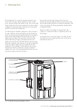
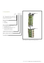
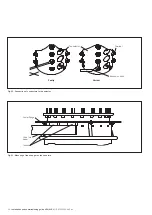
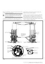
Fig. 9. Diverter switch UCL/VUCL and tap selector, size III.

F–F

B–B

D–D

E–E

A–A

F

F

D

C

C

A

B

B

A

D

E

E

Conductors

Diverter switch 
housing

Contact no. 30

Current 
collector

Tap selector

Insulating 
stud M16x120

Cleats

Insulating 
nut M16

Drive pin for the 
tap selector

Slot in the large gear wheel of the 
diverter switch housing

Shielding rings

Insulating shaft

C–C, 2 // conductors

C–C, single conductor

Locking nut M12

Spring washer

Socket head cap screw

Washer 14x30x2.5

Shielding ring (if the 
impulse withstand 
voltage to ground 

exceeds 380 kV)

Washers 14x30x2.5

Socket head cap screw

Spring washers

Socket head cap 

screw M8x25 (x4)

Locking nut M8

Socket head cap

screw M10x40 (x4)

Spring washer

Washer 10.5x24x3 (x4) 

Tap selector

Diverter switch housing

Conductors

Socket head cap 
screw M12

Locking nut M12

Spring washer

Washer 14x30x2.5

Spring washer

Locking nut M12

Shielding ring, 
TS 11

Содержание UCL

Страница 1: ...On load tap changers type UCL and VUCL Installation and commissioning guide 1ZSC000562 AAZ en...

Страница 2: ...ntative ABB makes no warranty or representation and assumes no liability for the accuracy of the information in this document or for the use of such information All information in this document is sub...

Страница 3: ...described and to provide trouble free operation Safety precautions WARNING Unused transformer oil is harmful Fumes from unused warm oil may irritate the respiratory organs and the eyes After long and...

Страница 4: ...is 135 C 275 F CAUTION Use the special bottom valve key only delivered with the tap changer to operate the bottom valve through the oil draining tube The use of a stiffer tool may damage the valve CAU...

Страница 5: ...d during electrical operation WARNING If the tap changer is not at its exact position and the hand crank is pulled out the motor drive mechanism will start and go to the exact position if the power su...

Страница 6: ...transformer cover after the drying process 23 3 3 Connection to terminals 25 3 4 Transformer ratio measurement 27 3 4 1 Transformer ratio measurement before drying 27 3 4 2 Transformer ratio measureme...

Страница 7: ...t 46 8 2 1 Transformer filled with oil 46 8 2 1 1 Conservator mounted 46 8 2 1 2 Conservator unmounted 46 8 2 2 Transformer drained 46 8 2 2 1 Conservator mounted 46 8 2 2 2 Conservator unmounted 46 9...

Страница 8: ......

Страница 9: ...former manufacturer to connect the windings to the tap changer before drying and without having the transformer cover mounted The transformer cover is then lowered onto the tank and the tap changer is...

Страница 10: ...ective tubes Shielding caps only for insulation level above 380 kV Type of connection N or E Hand crank inside the cover Motor drive mechanism Bevel gear Shielding rings only for insulation level abov...

Страница 11: ...Example UCLRE 650 900 III Type of switching L Linear R Plus Minus D Coarse Fine Type of connection N Three phase star point one unit E Single phase one unit T Three phase fully insulated three units...

Страница 12: ...or for both the transformer and the tap changer this can be ordered from ABB 1 4 Oil The oil quality should be I 30 according to IEC 60296 2012 and comply with IEC 60422 2008 Upon commissioning the br...

Страница 13: ...2x260 1370 650 600 900 890 2x300 1490 1050 600 900 910 2x340 1590 UCL E 380 600 900 410 260 670 380 1800 450 260 710 380 2400 480 260 740 650 600 900 430 300 730 650 1800 470 300 770 650 2400 500 300...

Страница 14: ...commended that photographs be taken of the damaged parts Mark the photos with ABB s reference number and the serial number of the tap changer and send them to ABB 3 Check that the parts delivered type...

Страница 15: ...d WARNING The intermediate gear and the insulating shaft of the diverter switch housing moves during operation Maintain a safe distance during operation to avoid injuries The diverter switch housing a...

Страница 16: ...lding rings lower the diverter switch housing very carefully and cover the flange in the transformer cover next to the insulating shaft of the diverter switch housing and diametrically opposed area wh...

Страница 17: ...tors between the diverter switch housing and tap selector The conductor ends and their connecting points have the same markings Fasten the conductors with cleats The number of conductors varies depend...

Страница 18: ...ter switch housing Shielding rings Insulating shaft C C 2 conductors C C single conductor Locking nut M12 Spring washer Socket head cap screw Washer 14x30x2 5 Shielding ring if the impulse withstand v...

Страница 19: ...nt in the yoke fork when the transformer is in operation Mounting of the tap changer on the yoke fork can be carried out by two alternative methods depending on when the transformer ratio measurement...

Страница 20: ...tom valve let the bottom valve key DS16 slide down through the oil drainage tube and when it has gripped the valve rotate it in a counter clockwise direction until it stops after approximately 6 turns...

Страница 21: ...The drive shaft must not be rotated 11 The guide bar for positioning the diverter switch in the housing is secured in the upper flange with screws and washers Remove the screws and washers Store the...

Страница 22: ...ce must be tilted when attaching Lift the tap changer onto the yoke fork Place the tap changer in position for mounting the outer shaft system see transformer drawing Insert the supplied guide bolts D...

Страница 23: ...ed Retighten all nuts to 24 5 Nm After tightening the nuts remove the lifting device 7 Place the O ring for the bevel gear in its groove in the upper flange see Fig 17 Remount the bevel gear unit in t...

Страница 24: ...L 1ZSC000562 AAZ en Attachment clamps Fig 17 Slot in drive shaft O ring Pin Oil drainage tube Fig 18 Plug 40 Nm Spring washer Locking nut M8 20x Flat washer 8 4x20x2 Yoke fork Lower flange O ring Uppe...

Страница 25: ...he tap selector shall be insulated by winding paper around them to a thickness of 3 mm see Fig 7 The paper should be of the same quality as used for insulating conductors within the active part of the...

Страница 26: ...ssioning guide UCL VUCL 1ZSC000562 AAZ en Faulty Correct Tap selector Expansion bend Terminal Fig 20 Connection of conductors to the selector Yoke fork beam Inserts Lower flange Fig 21 Mounting of tap...

Страница 27: ...erter switch is installed incorrectly or the tap changer is not correctly connected to the winding 3 4 1 Transformer ratio measurement before drying 1 Remove the locking device from the gear unit on t...

Страница 28: ...t the bottom valve key is removed after the valve has been closed 2 The cleats on the upper section of the tap selector that hold the conductors between the diverter switch housing and the tap selecto...

Страница 29: ...irection while pushing down the diverter switch For UCL it may be necessary to push and pull the lifting device for the diverter switch a little back and forth while pushing down The top part of the d...

Страница 30: ...rmer should be level within 1 mm If adjustment is needed shims should be used 2 Install the bevel gear SA 21 on the edge of the transformer cover see Fig 26 3 Check that the position indicator on the...

Страница 31: ...ssioning guide UCL VUCL 31 Fig 24 Position alignment for UCL VUCL with motor drive mechanism BUE Transformer Position indicator Adjustment nuts Brake disc Brake assembly The same indicated tap positio...

Страница 32: ...14 15 16 17 18 19 Fig 25 Position alignment for UCL VUCL with motor drive mechanism type BUL Exact position Max deviation Transformer Roller on the brake arm in the notch of the cam disc Contra nut A...

Страница 33: ...l protective tube SA 17 Clamp SA 18 Hex head bolt M10 SA 19 Washer SA 20 O ring SA 21 Bevel gear SA 22 Horizontal square shaft for unit 1 SA 23 Horizontal protective tube for unit 1 SA 24 Horizontal p...

Страница 34: ...e motor drive mechanism with a hose clip Leave about 3 mm of play to the flange ring for water drainage The tube with the larger diameter is mounted on the bevel gear Tighten the two screws A and then...

Страница 35: ...ssioning guide UCL VUCL 35 SA10 SA10 SA15 SA16 SA21 SA11 SA14 SA15 SA16 SA10 SA10 SA15 SA27 SA28 SA26 SA29 BUL A SA12 SA13 SA11 A BUE K2 SA14 Fig 28 Fig 29 Drive pin Fig 30 Fig 27 Square shaft Fig 32...

Страница 36: ...halves see Fig 31 Lightly tighten the screws and check that the shaft can be moved approximately 2 mm in the axial direction axial play Check the dimension shown in Fig 30 Tighten the two screws A fi...

Страница 37: ...4 Fig 35 Fig 36 Locking device single unit tap changer K1 SA14 SA24 SA10 SA23 SA11 LB1 Slotted end Drive pin M8 screw Disc Locking device Fig 37 Fig 38 A SA10 Slot SA24 SA23 SA21 Spherical coupling pa...

Страница 38: ...e cover SA33 Tighten the two set screws taken from the locking device see Fig 43 5 2 3 Mounting of horizontal drive shaft for two units The following applies to the fitting of drive shafts and their p...

Страница 39: ...g guide UCL VUCL 39 Fig 43 Locking device and cover multiple unit tap changer Cover SA 33 Locking device Set screws SA12 SA13 SA11 SA32 SA30 SA31 Coupling Disc A SA10 SA10 Fig 41 SA10 SA10 SA32 SA25 S...

Страница 40: ...the same position 2 Remove the locking device for the motor drive mechanism see Fig 44 Locking device BUE BUL Fig 44 Locking device for motor drive mechanism If transformer ratio measurement is to be...

Страница 41: ...able ground level Fig 47 Extra oil sampling valve The valve is removed and then refitted at the end of the sampling tube Fig 45 Oil valve Fig 46 Sample pipe dimensions Extra oil valve shall be removed...

Страница 42: ...til the conservator is filled to its correct level Also see Section 1 5 7 Shut the oil valve and disconnect the pump 8 Refit the breathing device Make sure that the connection to the breathing device...

Страница 43: ...000562 AAZ en Installation and commissioning guide UCL VUCL 43 75 5 7 20 44 2 Vacuum Tap changer Oil Fig 49 Oil filling under vacuum Oil Transformer Fig 48 Assembly O ring Stud M10 O ring Pipe connect...

Страница 44: ...n The motor drive mechanism will stop when it has made approximately half of the complete operation and will operate back and forth without the tap changer changing position until the control selector...

Страница 45: ...shafts for two units 1 Detach the protective cover SA33 on the bevel gear of unit 2 and lock the bevel gear with the locking device marked 2 and two set screws see Fig 36 2 Loosen the hose clips holdi...

Страница 46: ...ervator 8 2 2 2 Conservator unmounted Drain the oil as described in Section 8 2 2 1 Now remove the conservator connection Seal the diverter switch housing against ambient air by fitting covers with ga...

Страница 47: ...ide there should be no need for adjustments If necessary Sections 5 1 and 5 2 provide complete information for fitting and adjusting of the shaft system The arrangement of the drive shaft system is sh...

Страница 48: ...SA14 with protective tubes SA15 and SA16 and hose clips according to Fig 28 Connect the square shaft with the mounted coupling halves to the motor drive Mount two coupling halves SA11 to the other en...

Страница 49: ...or both of them show the same position The motor drive mechanism is at the exact position since the steps in Section 9 2 2 have been carried out The tap changer is at the exact position when the windo...

Страница 50: ...t 5 See Figs 24 and 25 The motor drive mechanism and the tap changer should have the same indicated tap position and be at their exact positions The motor drive mechanism and the tap changer are at th...

Страница 51: ...p changer and the motor drive mechanism at different operating positions may cause transformer failure The door of the motor drive mechanism can be locked with a padlock not included in the delivery D...

Страница 52: ...498 ABJ for VUCL 9 6 3 Counter Check that the counter is functioning for RAISE and LOWER operations 9 6 4 Position transmitter and other position switches Check the function of the position transmitte...

Страница 53: ......

Страница 54: ......

Страница 55: ......

Страница 56: ...s Copyright 2013 ABB All rights reserved 1ZSC000562 AAZ en 2013 10 30 ABB AB Components SE 771 80 Ludvika Sweden Phone 46 240 78 20 00 Fax 46 240 121 57 E Mail sales se abb com www abb com electricalc...

Отзывы: