background image

88

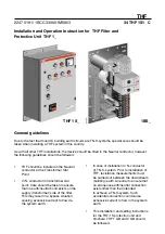
Before the connection to the network

1.

  Check that the connection have been made properly.

2.

  Check that no foreign parts are left during installation 

in the units.

3.

  Ensure the following values are set in the protective 

unit (see table).

4.

  Ensure the by-pass-switch is in OFF position.

5.

  Switch ON the control voltage in the protective unit.

6.

  Carry out a TEST-procedure (see table in page 9). 

If the indicator lights are according to the table in page 9, the protection unit is 
working correctly and the THF-filter can be switched on the network.

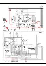
Current transformer KORE06F1600/1THF
Relay settings as factory settings in the above table:

- K4 relay setting 5 gives 50/60 Hz max. current: 300A
- K5 relay setting 1 gives 150/180 Hz max. current: 50A
The reaction time 0,5...0,7 sec.

After the connection to the network

Check that when the load is running the ‘’OK’’- light is ON.
Otherwise see the checklist in page 9.

The relay settings

Example:

Содержание THF Series

Страница 1: ...or in transformer star point Care should be taken to ensure that no earth neutral bond exists on the supply transformer side of the lter This may result in a bypass situation causing excessive current...

Страница 2: ...p to protect THF against overload The function of the protection unit The protection unit controls the by pass contactor K1 in case the 50 60Hz or 150 180Hz current exceeds the set level The factory s...

Страница 3: ...4 Measure the isolation resistance between pointA and B to ensure that the resistance between point A and B is high Re needs to be over 50 k Any earthing conductor with lower resistance by passing th...

Страница 4: ...be carried out between the downstream building earth neutral to ensure that no erroneous earth neutral connection exists other than that intended to achieve a TN S system Such accidental connection c...

Страница 5: ...l wiring rules suggesting to work all power off Prior to installation of THF in the transformer star point between point A and B following measures must be taken 1 Measure the fundamental 50 60Hz curr...

Страница 6: ...Installation to TN C S System THF in the transformer star point Recommended connecting point In PEN conductor in transformer star point Care should be taken to ensure that no earth neutral bond exists...

Страница 7: ...Prior to installation of THF in N conductor of one of the TN S parts resistance measurements must be carried out between the downstream building earth neutral to ensure that no erroneous earth neutra...

Страница 8: ...rocedure see table in page 9 If the indicator lights are according to the table in page 9 the protection unit is working correctly and the THF lter can be switched on the network Current transformer K...

Страница 9: ...he indicator light functions 3 Resetting of a protective unit 4 The indicator light functions in Test actions 1 Find out the reason why a protective unit has been activated and correct the fault The r...

Страница 10: ...10 10 0 8Nm M4 1 2Nm...

Страница 11: ...11 0 8Nm M4 1 2Nm...

Страница 12: ...THF 1BS_ THF 1S_ ABB Oy P O Box 622 Telephone 358 10 224 000 FIN 65101Vaasa Telefax 358 10 224 5708 Finland Low Voltage Products Teki Prepared 04 11 17 K Kimpim ki Tarkasti Checked Hyv ksyi Approved...

Отзывы: