background image

Manuel d'instructions - Produits ATEX - Série Conductivité TB82


ABB


TB82COND-ATEX-FR-A 

36


Содержание TB82EC

Страница 1: ...Operating Instructions Conductivity Transmitters ATEX multilingual version TB82EC Four Electrode TB82TE Two Electrode TB82TC Toroidal ...

Страница 2: ...ss system performance leading to personal injury or death Therefore comply fully with all Warning and Caution notices Information in this manual is intended only to assist our customers in the efficient operation of our equipment Use of this manual for any other purpose is specifically prohibited and its contents are not to be reproduced in full or part without prior approval of Technical Communic...

Страница 3: ...A Phone 7 75 883 4366 TAG Carson City NV OUTPUT TO SENSOR IS SUITABLE FOR NONINCENDIVE FIELD WIRING FOR CLASS I LOCATIONS WHEN USED WITH ABB SENSORS PER DRAWING P0806 CLASS I DIVISION 2 GROUPS A B C D CLASS II DIVISION 2 GROUPS E F G CLASS III INTRINSICALLY SAFE Exia T4 CLASS I DIVISION 1 GROUPS A B C D CLASS II DIVISION 1 GROUPS E F G CLASS III WHEN CONNECTED PER DRAWING P0806 Vmax 24V Imax 250mA...

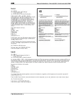
Страница 4: ...tzsystems gemäß Richtlinie 94 9 EG Das Fertigungsverfahren und die Lieferung dieses Geräts oder Schutzsystems unterliegen weiteren Anforderungen der Richtlinie die durch dieses Zertifikat nicht abgedeckt werden 12 Die Kennzeichnung des Geräts oder Schutzsystems muss Folgendes enthalten Ex II 1 G EEx ia IIC T4 Español 1 CERTIFICADO DE EXAMEN DE TIPO CE 2 Equipo o sistema de protección para uso en a...

Страница 5: ...hreibungen Technische Datei Nr A27 TB82ATEX ER02 002A Diese Datei umfasst 43 Punkte 97 Seiten Español A1 ANEXO A2 CERTIFICADO DE EXAMEN DE TIPO CE LCIE 02 ATEX 6115 X A3 Descripción del equipo o sistema de protección Los transmisores TB82 o ML82 proporcionan una señal de salida de 4 20 mA como respuesta a la salida del sensor de pH conectado xx82PH o del sensor de conductividad de cuatro electrodo...

Страница 6: ...und 2 sowie EN 50020 1994 Spezielle Parameter für den oder die betroffenen Schutzarten Individuelle Prüfungen und Tests Keine Español A1 ANEXO A2 CERTIFICADO DE EXAMEN DE TIPO CE LCIE 02 ATEX 6115 X continuación A5 Condiciones especiales para la utilización segura Los aparatos intrínsecamente seguros descritos anteriormente pueden instalarse en atmósferas explosivas El aparato debe combinarse únic...

Страница 7: ...ABB TB82 Conductivity Series ATEX Product Instruction Manual TB82COND ATEX EN A 7 Figure 2d ...

Страница 8: ...TB82 Conductivity Series ATEX Product Instruction Manual ABB 8 TB82COND ATEX EN A Figure 2d ...

Страница 9: ... choose a location that has ample clearance for the removal of the front bezel and rear cover The location should provide easy access for maintenance procedures and not be in a highly cor rosive environment Excessive mechanical vibrations and shocks as well as relay and power switches should not be in the immediate area Signal wiring should not be placed in conduit or open trays that contain power...

Страница 10: ...the grounding of the screen should be close to the power supply unit The specific noise immunity and emitted interference are only guaranteed when bus screening is fully effective e g ensuring that screening is maintained through any existing junction boxes Appropriate equi potential bonding must be provided to avoid differences in potential among the individual plant components To ensure fault fr...

Страница 11: ...Red Inner Electrode Black Outer Electrode Figure 11 Model TB2 and AC220 Two electrode Sensors Used with TB82TE Yellow and Blue Pt 100 or Pt 1000 TC Green Drive inner electrode Black Analog ground outer electrode Heavy Green Shield Figure 12 Model TB4 Four Electrode Sensors Used with TB82EC Yellow and Blue 3k ohm or 4 75k ohm TC Green Drive Black Drive Red Sense White Sense Heavy Green Shield Group...

Страница 12: ...D Green Yellow and Blue or T Terminal Blue and Green Yellow Blue Blue Yellow 6 RTD Brown or T Terminal Brown Yellow Yellow Heavy Green 7 Shield Screen None None Heavy Green Heavy Green None 8 Not Used None None None None Notes Models 2045 and 2077 sensors are supplied with terminals for wire connections Cable colors are given for ABB supplied cable P N 0233 811 for electrodes and 0233 819 for temp...

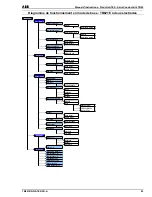
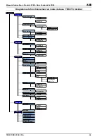
Страница 13: ...e one space to the right Decreases numeric values moves through a series of parameters Figure 16 shows the TB82 in the MEASURE mode of operation Pressing the key at the far right underneath the MENU icon provides access to all instrument functions Figure 17 shows the display after the MENU key has been pressed once The CALIBRATE menu can now be accessed by pressing the key underneath the SELECT ic...

Страница 14: ...20 mA OUT HOLD Hold Output Release Hold Hold to XXX Rerange Output 4 mA Point 20 mA Point Damping XX X Seconds CONFIGURE Modify View Basic Analyzer Group A Group B Group C Temp Sensor None 3k Balco Pt 100 4 7k RTD Temp Comp Type Manual Auto Standard KCl TC Coefficient enter o C Output 4 mA Point 20 mA Point Damping Enter Seconds Diagnostics On or Off Safe Mode Fail Low Fail High SECURITY Set Level...

Страница 15: ...just 20 mA OUT HOLD Hold Output Release Hold Hold to XXX Rerange Output 4 mA Point 20 mA Point Damping XX X Seconds CONFIGURE Modify View Basic Analyzer Cell Constant Temp Sensor None 3k Balco Pt 100 Pt 1000 Temp Comp Type Manual Auto Standard KCl TC Coefficient enter o C Output 4 mA Point 20 mA Point Damping Enter Seconds Diagnostics On or Off Safe Mode Fail Low Fail High SECURITY Set Level Calib...

Страница 16: ...ust 4 mA Adjust 20 mA OUT HOLD Hold Output Release Hold Hold to XXX Rerange Output 4 mA Point 20 mA Point Damping XX X Seconds CONFIGURE Modify View Basic Analyzer Type Temp Sensor None 3k Balco Pt 100 Pt 1000 Temp Comp Type Manual Auto Standard KCl TC Coefficient enter o C Output 4 mA Point 20 mA Point Damping Enter Seconds Diagnostics On or Off Safe Mode Fail Low Fail High SECURITY Set Level Cal...

Страница 17: ...aCl 0 18 weight HCl 0 20 weight H2SO4 User defined via non linear function generator ppm ppb or units of choice Analyzer input Group A Sensor Group B Sensor Group C Sensor Temperature Sensor 3k ohm Balco None Pt 100 RTD 4 75k ohm RTD Temperature Compensation Type Manual Auto Standard KCl Coefficient 0 to 9 99 C NaOH NaCl H2SO4 HCl Pure water neutral Pure water basic Pure water acidic User defined ...

Страница 18: ...sition Program X1 cond Y1 conc through X6 Y6 NaOH NaCl HCl H2SO4 Temp Sensor 3k Balco Pt 100 4 7 RTD None Temp Comp Type Manual Reference Temp o C Auto Standard KCl TC Coefficient Enter C NaOH NaCl HCl H2SO4 User Defined Group C Sensor Pure Water Neutral Acid Base Output 4 mA Point 20 mA Point Damping Enter Seconds Diagnostics On or Off Safe Mode Fail Low Fail High Adjust numerals decimal point an...

Страница 19: ...e temperature other than 25 C Pure water neutral for 0 01 Cell Constant Pure water basic for 0 01 Cell Constant Pure water acidic for 0 01 Cell Constant User defined Manual to a temperature other than 25 C 0 01 Cell Constant 4 mA 00 0 µS cm 20 mA 199 9 µS cm 0 10 Cell Constant 4 mA 00 0 µS cm 20 mA 1999 µS cm Output 1 00 Cell Constant 4 mA 00 0 mS cm 20 mA 19 99 mS cm Conductivity adjustable from ...

Страница 20: ... point position Program X1 cond Y1 conc through X6 Y6 Temp Sensor Pt 1000 None Pt 100 3k Balco RTD Temp Comp Type Manual Reference Temp o C Auto Standard KCl TC Coefficient Enter C User Defined 0 01 Cell Constant Pure Water Neutral Acid Base Output 4 mA Point 20 mA Point Damping Enter Seconds Diagnostics On or Off Safe Mode Fail Low Fail High Spike Spike Magnitude Adjust numerals decimal point and...

Страница 21: ...m Balco None Pt 100 RTD Pt 1000 RTD Temperature Compensation Type Manual Auto Standard KCl Coefficient 0 to 9 99 C NaOH NaCl H2SO4 HCl User defined Manual to a temperature other than 25 C Output 4 mA 0 000 mS cm 20 mA 1999 mS cm Conductivity adjustable from 0 100 0 µS cm to 1999 mS cm Concentration units minimum 1 weight span Damping 00 5 seconds Adjustable to 99 9 seconds Diagnostics Off On Safe ...

Страница 22: ... Decimal point position Program X1 cond Y1 conc through X6 Y6 Temp Sensor None 3k Balco RTD Pt 1000 Pt 100 Temp Comp Type Manual Reference Temp o C Auto Standard KCl TC Coefficient Enter C NaOH NaCl HCl H2SO4 User Defined Output 4 mA Point 20 mA Point Damping Enter Seconds Diagnostics On or Off Safe Mode Fail Low Fail High Spike Spike Magnitude Adjust numerals decimal point and units mS If configu...

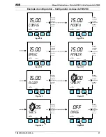
Страница 23: ...RITY DISPLAY 15 00 Basic exit to MEASURE SELECT NEXT mS cm MEASURE CALIBRATE OUT HOLD CONFIGURE SECURITY DISPLAY 15 00 ANALZR exit to MEASURE SELECT NEXT mS cm Figure 20 Figure 21 MEASURE CALIBRATE OUT HOLD CONFIGURE SECURITY DISPLAY 15 00 A grp exit to MEASURE ENTER NEXT mS cm MEASURE CALIBRATE OUT HOLD CONFIGURE SECURITY DISPLAY 0 00 4MA PT exit to MEASURE ENTER mS cm Figure 22 Figure 23 MEASURE...

Страница 24: ...ions are as follow 1000 µS cm 1 mS cm 1000 mS cm 1 S cm 1 S cm 100 S m Caution If a programming change has been made pressing the Exit to MEASURE key will activate the SAVE display Figure 28 YES and NO keys will also appear Press the YES key to save the changes If the NO key is pressed any configuration or programming changes will not be saved Note When changing digits such as in setting the 4 and...

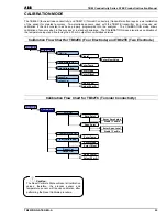
Страница 25: ...t and fine tuning the 4 20 mA output for non fieldbus versions Calibration Flow Chart for TB82EC Four Electrode and TB82TE Two Electrode Calibration Flow Chart for TB82TC Toroidal Conductivity Caution The Reset Calibrate State will reset all calibration values therefore the process sensor and temperature sensor will require calibration after performing the Reset Calibrate procedure MEASURE CALIBRA...

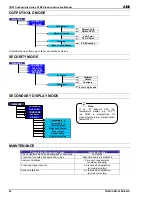
Страница 26: ...Preventative Maintenance Tasks Interval months Check tighten and clean all wiring and connections 12 months Clean and lubricate all gaskets and o rings Each time seals are disturbed Analyzer Validation Per user s requirements minimum annually Clean and inspect sensor As required by application minimum monthly Sensor calibration As required by application minimum monthly MEASURE CALIBRATE OUT HOLD ...

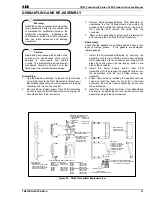
Страница 27: ...aptive screws per assembly using a bladed screwdriver Caution Dismantling and reassembly should not be carried out on site because of the risk of damage to components and printed circuits The dismantling and reassembly procedures should be carried out in the listed order to avoid instrument damage Warning Substitution of any components other than those assemblies listed in this section will compro...

Страница 28: ...re Output 0 1 C or less full scale at 95 relative humidity 0 01 mA C at 95 relative humidity Maximum Sensor Cable Length TB82EC 4 electrode TB82TC toroidal TB82TE 2 electrode Group A 30 5 m 100 ft Group B 15 2 m 50 ft Group C 7 6 m 25 ft 15 2 m 50 ft 30 5 m 100 ft Environmental Operating temperature LCD Range Storage temperature 20 to 60 C 4 to 140 F 20 to 60 C 4 to 140 F 40 to 70 C 40 to 158 F En...

Страница 29: ...Instructions d utilisation Transmetteur Série TB82 ATEX version française TB82EC à quatre électrodes TB82TE à deux électrodes TB82TC toroïdal ...

Страница 30: ...oriées sous les titres Avertissement et Attention Les informations contenues dans ce manuel sont destinées uniquement à aider nos clients à utiliser de façon efficace nos matériels L utilisation de ce manuel à d autres fins est explicitement interdite et son contenu ne doit pas être reproduit dans sa totalité ou partiellement sans l accord préalable du Service techniques de ABB Inc Avertissement U...

Страница 31: ...one 775 883 4366 TB82PHX2XXXXX 9 32 Vdc Profile Type 113 Carson City NV U S A Phone 7 75 883 4366 TAG Carson City NV OUTPUT TO SENSOR IS SUITABLE FOR NONINCENDIVE FIELD WIRING FOR CLASS I LOCATIONS WHEN USED WITH ABB SENSORS PER DRAWING P0806 CLASS I DIVISION 2 GROUPS A B C D CLASS II DIVISION 2 GROUPS E F G CLASS III INTRINSICALLY SAFE Exia T4 CLASS I DIVISION 1 GROUPS A B C D CLASS II DIVISION 1...

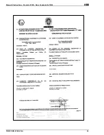
Страница 32: ...rüfung des genannten Geräts oder Schutzsystems gemäß Richtlinie 94 9 EG Das Fertigungsverfahren und die Lieferung dieses Geräts oder Schutzsystems unterliegen weiteren Anforderungen der Richtlinie die durch dieses Zertifikat nicht abgedeckt werden 12 Die Kennzeichnung des Geräts oder Schutzsystems muss Folgendes enthalten Ex II 1 G EEx ia IIC T4 Español 1 CERTIFICADO DE EXAMEN DE TIPO CE 2 Equipo ...

Страница 33: ...it Beschreibungen Technische Datei Nr A27 TB82ATEX ER02 002A Diese Datei umfasst 43 Punkte 97 Seiten Español A1 ANEXO A2 CERTIFICADO DE EXAMEN DE TIPO CE LCIE 02 ATEX 6115 X A3 Descripción del equipo o sistema de protección Los transmisores TB82 o ML82 proporcionan una señal de salida de 4 20 mA como respuesta a la salida del sensor de pH conectado xx82PH o del sensor de conductividad de cuatro el...

Страница 34: ...hang 1 und 2 sowie EN 50020 1994 Spezielle Parameter für den oder die betroffenen Schutzarten Individuelle Prüfungen und Tests Keine Español A1 ANEXO A2 CERTIFICADO DE EXAMEN DE TIPO CE LCIE 02 ATEX 6115 X continuación A5 Condiciones especiales para la utilización segura Los aparatos intrínsecamente seguros descritos anteriormente pueden instalarse en atmósferas explosivas El aparato debe combinar...

Страница 35: ...ABB Manuel d instructions Produits ATEX Série Conductivité TB82 TB82COND ATEX FR A 35 ...

Страница 36: ...Manuel d instructions Produits ATEX Série Conductivité TB82 ABB TB82COND ATEX FR A 36 ...

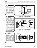
Страница 37: ...t doit permettre d accéder facilement à l instrument pour sa maintenance et ne pas se trouver dans un environnement hautement corrosif L instrument ne doit pas se trouver dans une zone soumise à des vibrations mécaniques et des chocs excessifs ni à proximité de relais et d interrupteurs d alimentation Le câblage du signal ne doit pas être placé dans un conduit ni sur un plateau ouvert contenant de...

Страница 38: ...mentés par bus la mise à la terre du blindage doit être réalisée à proximité de l unité d alimentation L immunité au bruit et la limitation des interférences ne sont garanties que lorsque la blindage du bus est totalement efficace c est à dire avec continuité dans tous les boîtiers de raccordement si existant Une liaison équipotentielle appropriée doit être réalisée pour éviter les différences de ...

Страница 39: ...ec le TB82TE Vert jaune bleu et brun Pt 100 TC Rouge électrode interne Noir électrode externe Figure 11 Capteurs TB2 et AC220 à deux électrodes utilisés avec le TB82TE Jaune et bleu Pt 100 ou Pt 1000 TC Vert alimentation électrode interne Noir terre analogique électrode Vert foncé gaine Figure 12 Capteur TB4 à quatre électrodes utilisé avec le TB82EC Rouge Jaune et bleu 3 kΩ ou 4 75 kΩ TC Vert ali...

Страница 40: ... et bleu ou borne T Bleu et vert jaune Bleu Bleu Yellow 6 RTD Brun ou borne T Brun Jaune Jaune Heavy Green 7 Shield Screen Aucun Aucun Vert foncé Vert foncé None 8 Not Used Aucun Aucun Aucun Aucun Remarque les capteurs 2045 et 2077 sont fournis avec un bornier de connexion des câbles Les couleurs indiquées correspondent à celles des câbles fournis par ABB pièce n 0233 811 pour les électrodes et 02...

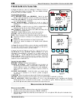
Страница 41: ...lace parmi différents parameters La Figure 16 présente le TB82 en mode de fonctionnement MEASURE Pour accéder à toutes les autres fonctions de l instrument appuyez sur la touche située le plus à droite sous l icône MENU La Figure 17 présente l affichage lorsque l on a appuyé une fois sur la touche MENU Il est désormais possible d accéder au menu CALIBRATE ETALONNER en appuyant sur la touche située...

Страница 42: ... Adjust 20 mA OUT HOLD Hold Output Release Hold Hold to XXX Rerange Output 4 mA Point 20 mA Point Damping XX X Seconds CONFIGURE Modify View Basic Analyzer Group A Group B Group C Temp Sensor None 3k Balco Pt 100 4 7k RTD Temp Comp Type Manual Auto Standard KCl TC Coefficient enter o C Output 4 mA Point 20 mA Point Damping Enter Seconds Diagnostics On or Off Safe Mode Fail Low Fail High SECURITY S...

Страница 43: ... 4 mA Adjust 20 mA OUT HOLD Hold Output Release Hold Hold to XXX Rerange Output 4 mA Point 20 mA Point Damping XX X Seconds CONFIGURE Modify View Basic Analyzer Cell Constant Temp Sensor None 3k Balco Pt 100 Pt 1000 Temp Comp Type Manual Auto Standard KCl TC Coefficient enter o C Output 4 mA Point 20 mA Point Damping Enter Seconds Diagnostics On or Off Safe Mode Fail Low Fail High SECURITY Set Lev...

Страница 44: ...n Adjust 4 mA Adjust 20 mA OUT HOLD Hold Output Release Hold Hold to XXX Rerange Output 4 mA Point 20 mA Point Damping XX X Seconds CONFIGURE Modify View Basic Analyzer Type Temp Sensor None 3k Balco Pt 100 Pt 1000 Temp Comp Type Manual Auto Standard KCl TC Coefficient enter o C Output 4 mA Point 20 mA Point Damping Enter Seconds Diagnostics On or Off Safe Mode Fail Low Fail High SECURITY Set Leve...

Страница 45: ...l utilisateur via le générateur de fonction non linéaire en ppm parts par million ppm parts par milliard ou en fonction des unités sélectionnées Entrée analyseur Capteur de groupe A Capteur de groupe B Capteur de groupe C Capteur de température Balco 3 kΩ Aucun Pt 100 RTD 4 75 kΩ RTD Température Type de compensation Manuel Auto KCl standard Coefficient 0 à 9 99 C NaOH NaCl H2SO4 HCl Eau pure neutr...

Страница 46: ...cimal Point Position Program X1 cond Y1 conc through X6 Y6 NaOH NaCl HCl H2SO4 Temp Sensor 3k Balco Pt 100 4 7 RTD None Temp Comp Type Manual Reference Temp o C Auto Standard KCl TC Coefficient Enter C NaOH NaCl HCl H2SO4 User Defined Group C Sensor Pure Water Neutral Acid Base Output 4 mA Point 20 mA Point Damping Enter Seconds Diagnostics On or Off Safe Mode Fail Low Fail High Adjust numerals de...

Страница 47: ...ente de 25 C Eau pure neutre pour constante de cellule 0 01 Eau pure alcaline pour constante de cellule 0 01 Eau pure acide pour constante de cellule 0 01 Défini par l utilisateur Manuel à une température différente de 25 C Constante de cellule 0 01 4 mA 00 0 µS cm 20 mA 199 9 µS cm Constante de cellule 0 10 4 mA 00 0 µS cm 20 mA 1 999 µS cm Sortie Constante de cellule 1 00 4 mA 00 0 mS cm 20 mA 1...

Страница 48: ...fined Decimal point position Program X1 cond Y1 conc through X6 Y6 Temp Sensor Pt 1000 None Pt 100 3k Balco RTD Temp Comp Type Manual Reference Temp o C Auto Standard KCl TC Coefficient Enter C User Defined 0 01 Cell Constant Pure Water Neutral Acid Base Output 4 mA Point 20 mA Point Damping Enter Seconds Diagnostics On or Off Safe Mode Fail Low Fail High Spike Spike Magnitude Adjust numerals deci...

Страница 49: ...Balco 3 kΩ Aucun Pt 100 RTD Pt 1000 RTD Température Type de compensation Manuel Auto KCl standard Coefficient 0 à 9 99 C NaOH NaCl H2SO4 HCl Défini par l utilisateur Manuel à une température différente de 25 C Sortie 4 mA 0 000 mS cm 20 mA 1 999 mS cm Conductivité réglable de 0 100 0 µS cm à 1 999 mS cm Unités de concentration minimum 1 plage poids Amortissement 00 5 seconde Réglable à 99 9 second...

Страница 50: ...user defined Decimal point position Program X1 cond Y1 conc through X6 Y6 Temp Sensor None 3k Balco RTD Pt 1000 Pt 100 Temp Comp Type Manual Reference Temp o C Auto Standard KCl TC Coefficient Enter C NaOH NaCl HCl H2SO4 User Defined Output 4 mA Point 20 mA Point Damping Enter Seconds Diagnostics On or Off Safe Mode Fail Low Fail High Spike Spike Magnitude Adjust numerals decimal point and units m...

Страница 51: ...E SECURITY DISPLAY 15 00 Basic exit to MEASURE SELECT NEXT mS cm MEASURE CALIBRATE OUT HOLD CONFIGURE SECURITY DISPLAY 15 00 ANALZR exit to MEASURE SELECT NEXT mS cm Figure 20 Figure 21 MEASURE CALIBRATE OUT HOLD CONFIGURE SECURITY DISPLAY 15 00 A grp exit to MEASURE ENTER NEXT mS cm MEASURE CALIBRATE OUT HOLD CONFIGURE SECURITY DISPLAY 0 00 4MA PT exit to MEASURE ENTER mS cm Figure 22 Figure 23 M...

Страница 52: ...n si suite à un changement de programmation vous appuyez sur Exit to MEASURE sortir pour MESURER l écran SAVE ENREGISTRER s affiche Figure 28 Les touches YES Oui et NO Non s affichent également Appuyez sur YES Oui si vous souhaitez enregistrer les modifications Appuyez sur NO Non si vous ne souhaitez pas que les changements de configuration ou de programmation soient pris en compte Remarque lors d...

Страница 53: ...age de l entrée de température et de régler avec précision la sortie 4 20 mA des versions non fieldbus Diagramme d étalonnage des TB82EC quatre électrodes et TB82TE deux électrodes Diagramme d étalonnage du TB82TC conductivité toroïdale Attention la fonction de réinitialisation restaure toutes les valeurs d étalonnage il faut donc faire suivre la procédure de réinitialisation par un étalonnage des...

Страница 54: ...t nettoyer tous les câbles et connexions 12 mois Nettoyer et lubrifier tous les joints toriques et d étanchéité Chaque fois que les joints sont desserrés Validation de l analyseur Selon les impératifs de l utilisateur au minimum tous les ans Nettoyer et examiner le capteur En fonction des besoins de l application au minimum tous les mois Etalonnage du capteur En fonction des besoins de l applicati...

Страница 55: ...t le démontage ne doivent pas être effectués sur site en raison du risque de détérioration des composants et des circuits imprimés Les opérations de montage et de démontage doivent être réalisées en suivant l ordre indiqué pour éviter d endommager l instrument Avertissement La substitution de tout composant par des éléments non mentionnés dans cette section risque de compromettre la certification ...

Страница 56: ...ations homologuées Courant au repos 15 mA 9 à 32 VCC 9 à 24 VCC pour les applications homologuées Courant au repos 15 mA Longueur maximale du câble de capteur TB82EC 4 électrodes TB82TC toroïdal TB82TE 2 électrodes Groupe A 30 5 m 100 pi Groupe B 15 2 m 50 pi Groupe C 7 6 m 25 pi 15 2 m 50 pi 30 5 m 100 pi Classification de l enceinte NEMA 4X IP65 Dimensions Hauteur Profondeur minimale du panneau ...

Страница 57: ...Bedienungs anleitung Messumformer der Deutsche ATEX Version Serie TB82 TB82EC mit vier Elektroden TB82TE mit zwei Elektroden TB82TC induktiver Leitfähigkeitssensor ...

Страница 58: ...wendig alle Hinweise die mit Warnung und Vorsicht gekennzeichnet sind genau zu beachten Die Informationen in dieser Bedienungsanleitung sollen den Anwender lediglich beim effizienten Betrieb unserer Geräte unterstützen Die Verwendung der Bedienungsanleitung zu anderen Zwecken als den angegebenen ist ausdrücklich verboten Der Inhalt darf weder ganz noch teilweise ohne vorherige Genehmigung durch da...

Страница 59: ...R IS SUITABLE FOR NONINCENDIVE FIELD WIRING FOR CLASS I LOCATIONS WHEN USED WITH ABB SENSORS PER DRAWING P0806 CLASS I DIVISION 2 GROUPS A B C D CLASS II DIVISION 2 GROUPS E F G CLASS III INTRINSICALLY SAFE Exia T4 CLASS I DIVISION 1 GROUPS A B C D CLASS II DIVISION 1 GROUPS E F G CLASS III WHEN CONNECTED PER DRAWING P0806 Vmax 24V Imax 250mA Ci 0 Li 0mH 82 TWO WIRE TRANSMITTER SERIES 2175 LOCKHEE...

Страница 60: ...rüfung und die Prüfung des genannten Geräts oder Schutzsystems gemäß Richtlinie 94 9 EG Das Fertigungsverfahren und die Lieferung dieses Geräts oder Schutzsystems unterliegen weiteren Anforderungen der Richtlinie die durch dieses Zertifikat nicht abgedeckt werden 12 Die Kennzeichnung des Geräts oder Schutzsystems muss Folgendes enthalten Ex II 1 G EEx ia IIC T4 Español 1 CERTIFICADO DE EXAMEN DE T...

Страница 61: ...4 Dokumente mit Beschreibungen Technische Datei Nr A27 TB82ATEX ER02 002A Diese Datei umfasst 43 Punkte 97 Seiten Español A1 ANEXO A2 CERTIFICADO DE EXAMEN DE TIPO CE LCIE 02 ATEX 6115 X A3 Descripción del equipo o sistema de protección Los transmisores TB82 o ML82 proporcionan una señal de salida de 4 20 mA como respuesta a la salida del sensor de pH conectado xx82PH o del sensor de conductividad...

Страница 62: ...50014 1997 Anhang 1 und 2 sowie EN 50020 1994 Spezielle Parameter für den oder die betroffenen Schutzarten Individuelle Prüfungen und Tests Keine Español A1 ANEXO A2 CERTIFICADO DE EXAMEN DE TIPO CE LCIE 02 ATEX 6115 X continuación A5 Condiciones especiales para la utilización segura Los aparatos intrínsecamente seguros descritos anteriormente pueden instalarse en atmósferas explosivas El aparato ...

Страница 63: ...ABB Bedienungsanleitung zu den ATEX konformen Leitfähigkeits Analysatoren der Serie TB82 TB82COND ATEX DE A 63 ...

Страница 64: ...Bedienungsanleitung zu den ATEX konformen Leitfähigkeits Analysatoren der Serie TB82 ABB 64 TB82COND ATEX DE A ...

Страница 65: ...die genügend Raum zum Abnehmen des Frontrah mens und der rückwärtigen Abdeckung bietet Der Montageort soll den einfachen Zugang für Wartungs maßnahmen ermö glichen und sich nicht in einer korrosiven Umgebung befinden Über mäßige mechanische Ersch ütterungen sowie Relais und Ein Aus Schalter sollten sich nicht in unmittelbarer Nähe befinden Die Signalkabel sollen nicht in Isolierrohren oder offenen...

Страница 66: ...usgestrahlten Störungen ist nur dann gewährleistet wenn die Abschirmung des Busses voll wirksam ist Es ist beispielsweise sicherzustellen dass die Abschirmung durch die vorhandenen Anschlusskästen aufrechterhalten wird Um Abweichungen beim Potential zwischen den verschiedenen Komponenten der Anlage zu vermeiden ist eine geeignete Equipotentialverbindung erforderlich Zur fehlerfreien Kommunikation ...

Страница 67: ...2089 in Verbindung mit TB82TE Abbildung 11 2 Elektroden Sensoren der Reihen TB2 und AC220 in Verbindung mit TB82TE Grün gelb blau und braun Pt 100 TC Rot Innenelektrode Schwarz Außenelektrode Gelb und blau Pt 100 oder Pt 1000 TC Grün Strom Innenelektrode Schwarz Erdung Außenelektrode Dunkelgrün Abschirmung Abbildung 12 4 Elektroden Sensoren der Reihe TB4 in Verbindung mit TB82EC Rot Gelb und blau ...

Страница 68: ...lue 5 RTD Grüner gelber und blauer Anschluss T Anschluss Blau und grün gelb Blau Blau Yellow 6 RTD Brauner Anschluss T Anschluss Braun Gelb Gelb Heavy Green 7 Shield Screen Keine Keine Dunkelgrün Dunkelgrün None 8 Not Used Keine Keine Keine Keine Hinweise Sensoren der Reihen 2045 und 2077 werden mit Anschlüssen für Kabelstecker geliefert Die Farben der Kabel beziehen sich auf die von ABB mitgelief...

Страница 69: ...Beim erneuten Drücken der Taste MENU MENÜ wechselt das Display zur nächsten Funktion in diesem Fall OUT HOLD AUS HALTEN Durch erneutes Drücken wird die Option CONFIGURE KONFIGURIEREN aktiviert usw Es stehen sechs Funktionen unter MENU MENÜ zur Auswahl MEASURE MESSEN Normales Betriebsdisplay CALIBRATE KALIBRIEREN Ermöglicht die Kalibrierung der Leitfähigkeits und Temperatursensoren das Zurücksetzen...

Страница 70: ...ion Adjust 4 mA Adjust 20 mA OUT HOLD Hold Output Release Hold Hold to XXX Rerange Output 4 mA Point 20 mA Point Damping XX X Seconds CONFIGURE Modify View Basic Analyzer Group A Group B Group C Temp Sensor None 3k Balco Pt 100 4 7k RTD Temp Comp Type Manual Auto Standard KCl TC Coefficient enter o C Output 4 mA Point 20 mA Point Damping Enter Seconds Diagnostics On or Off Safe Mode Fail Low Fail ...

Страница 71: ...ibration Adjust 4 mA Adjust 20 mA OUT HOLD Hold Output Release Hold Hold to XXX Rerange Output 4 mA Point 20 mA Point Damping XX X Seconds CONFIGURE Modify View Basic Analyzer Cell Constant Temp Sensor None 3k Balco Pt 100 Pt 1000 Temp Comp Type Manual Auto Standard KCl TC Coefficient enter o C Output 4 mA Point 20 mA Point Damping Enter Seconds Diagnostics On or Off Safe Mode Fail Low Fail High S...

Страница 72: ...ibration Output Calibration Adjust 4 mA Adjust 20 mA OUT HOLD Hold Output Release Hold Hold to XXX Rerange Output 4 mA Point 20 mA Point Damping XX X Seconds CONFIGURE Modify View Basic Analyzer Type Temp Sensor None 3k Balco Pt 100 Pt 1000 Temp Comp Type Manual Auto Standard KCl TC Coefficient enter o C Output 4 mA Point 20 mA Point Damping Enter Seconds Diagnostics On or Off Safe Mode Fail Low F...

Страница 73: ...0 Gewichts NaCl 0 18 Gewichts HCl 0 20 Gewichts H2SO4 Mit Kurvenbildner für nichtlinearen Ausgang erzeugte benutzerdefinierte Werte in ppm ppb oder einer beliebig wählbaren Einheit Analysator Eingang Sensor Gruppe A Sensor Gruppe B Sensor Gruppe C Temperatursensor Balco 3000 Ohm Keine Pt 100 Wth Wth 4750 Ohm Temperatur kompensationstyp Manuell Auto KCl Standardkoeffizient 0 bis 99 C NaOH NaCl H2SO...

Страница 74: ...ser defined Decimal Point Position Program X1 cond Y1 conc through X6 Y6 NaOH NaCl HCl H2SO4 Temp Sensor 3k Balco Pt 100 4 7 RTD None Temp Comp Type Manual Reference Temp o C Auto Standard KCl TC Coefficient Enter C NaOH NaCl HCl H2SO4 User Defined Group C Sensor Pure Water Neutral Acid Base Output 4 mA Point 20 mA Point Damping Enter Seconds Diagnostics On or Off Safe Mode Fail Low Fail High Adju...

Страница 75: ...99 C Andere Referenztemperatur als 25 C Reinwasser neutral für Zellkonstante 0 01 Reinwasser basisch für Zellkonstante 0 01 Reinwasser sauer für Zellkonstante 0 01 Benutzerdefiniert Manuell für andere Temperaturen als 25 C Zellkonstante 0 01 4 mA 00 0 µS cm 20 mA 199 9 µS cm Zellkonstante 0 10 4 mA 00 0 µS cm 20 mA 1999 µS cm Ausgang Zellkonstante 1 00 4 mA 00 0 mS cm 20 mA 19 99 mS cm Leitfähigke...

Страница 76: ... ppm ppb user defined Decimal point position Program X1 cond Y1 conc through X6 Y6 Temp Sensor Pt 1000 None Pt 100 3k Balco RTD Temp Comp Type Manual Reference Temp o C Auto Standard KCl TC Coefficient Enter C User Defined 0 01 Cell Constant Pure Water Neutral Acid Base Output 4 mA Point 20 mA Point Damping Enter Seconds Diagnostics On or Off Safe Mode Fail Low Fail High Spike Spike Magnitude Adju...

Страница 77: ...eratursensor Balco 3000 Ohm Keine Pt 100 Wth Pt 1000 Wth Temperatur kompensationstyp Handbuch Auto KCl Standardkoeffizient 0 bis 99 C NaOH NaCl H2SO4 HCl Benutzerdefiniert Manuell für andere Temperaturen als 25 C Ausgang 4 mA 0 000 mS cm 20 mA 1999 mS cm Leitfähigkeit verstellbar von 0 100 0 µS cm bis 1999 mS cm Konzentrationseinheiten mind 1 Gewichtsbereich Dämpfung 00 5 Sekunden Bis auf 99 9 Sek...

Страница 78: ...User defined Units ppm ppb user defined Decimal point position Program X1 cond Y1 conc through X6 Y6 Temp Sensor None 3k Balco RTD Pt 1000 Pt 100 Temp Comp Type Manual Reference Temp o C Auto Standard KCl TC Coefficient Enter C NaOH NaCl HCl H2SO4 User Defined Output 4 mA Point 20 mA Point Damping Enter Seconds Diagnostics On or Off Safe Mode Fail Low Fail High Spike Spike Magnitude Adjust numeral...

Страница 79: ...OLD CONFIGURE SECURITY DISPLAY 15 00 Basic exit to MEASURE SELECT NEXT mS cm MEASURE CALIBRATE OUT HOLD CONFIGURE SECURITY DISPLAY 15 00 ANALZR exit to MEASURE SELECT NEXT mS cm Figure 20 Figure 21 MEASURE CALIBRATE OUT HOLD CONFIGURE SECURITY DISPLAY 15 00 A grp exit to MEASURE ENTER NEXT mS cm MEASURE CALIBRATE OUT HOLD CONFIGURE SECURITY DISPLAY 0 00 4MA PT exit to MEASURE ENTER mS cm Figure 22...

Страница 80: ... 100 S m Achtung Wenn die Einstellungen verändert werden wird beim Drücken der Taste Exit to MEASURE Beenden und weiter zu MESSEN gefragt ob die Änderungen gespeichert werden sollen Abbildung 28 Dazu werden die Auswahlmöglichkeiten YES JA und NO NEIN eingeblendet Zum Speichern der Änderungen drücken Sie auf YES Wenn Sie auf NO drücken gehen sämtliche Änderungen an Konfiguration oder Programmierung...

Страница 81: ...mperatureingangs und bei Ausführungen ohne Feldbus die Feineinstellung für den 4 bis 20 mA Ausgang festgelegt Ablaufdiagramm für TB82EC mit vier Elektroden und TB82TE mit zwei Elektroden Ablaufdiagramm für TB82TC induktiver Leitfähigkeitssensor Achtung Mit Reset Calibrate State Kalibrierung zurücksetzen werden alle Kalibrierungseinstellungen zurückgesetzt Die Leitfähigkeits und Temperatursensoren ...

Страница 82: ...rbeugende Wartungsmaßnahmen Intervall Monate Alle Kabel und Verbindungen prüfen anziehen und reinigen 12 Monate Alle Dichtungen und O Ringe reinigen und abschmieren Bei jedem Lockern der Dichtungen Validierung des Analysators Nach Bedarf mindestens jährlich Sensor reinigen und prüfen Gemäß den Anforderungen der Anwendung mindestens monatlich Sensorkalibrierung Gemäß den Anforderungen der Anwendung...

Страница 83: ...tzschraubendreher festziehen Vorsicht Die Zerlegung und der Zusammenbau dürfen nicht vor Ort erfolgen weil dies zu einer Beschädigung der Komponenten und Platinen führen kann Die Verfahren für Zerlegung und Zusammenbau sind in der angegebenen Reihenfolge auszuführen um so eine Beschädigung des Geräts zu vermeiden Abb 29 Zusammenbauzeichnung des Messumformers TB82 MIKROPROZESSOR DISPLAY BAUGRUPPEN ...

Страница 84: ... bis 24 V DC für zugelassene Anwendungen 15 mA Ruhestrom 9 bis 32 V DC 9 bis 24 V DC für zugelassene Anwendungen 15 mA Ruhestrom Maximale Länge der Sensorkabel TB82EC 4 Elektroden TB82TC induktiv TB82TE 2 Elektroden Gruppe A 30 5 m Gruppe B 15 2 m Gruppe C 7 6 m 15 2 m 30 5 m Umgebungsbedingungen Betriebstemperatur LCD Bereich Lagertemperatur 20 bis 60 C 20 bis 60 C 40 bis 70 C Gehäuse Schutzart N...

Страница 85: ...Istruzioni per l uso Serie TB82 ATEX Versione Italiano TB82EC a quattro elettrodi TB82TE a due elettrodi TB82TC toroidale ...

Страница 86: ...tema del processo conducendo a lesioni personali o morte Pertanto si consiglia di uniformarsi completamente a quanto riportato in tutti i messaggi di Avvertenza e Attenzione Le informazioni in questo manuale hanno il solo scopo di assistere l utente nell ottenere un funzionamento efficiente dell apparecchiatura È proibito usare questo manuale per qualsiasi altro scopo così come è proibita la ripro...

Страница 87: ...B82PHX2XXXXX 9 32 Vdc Profile Type 113 Carson City NV U S A Phone 7 75 883 4366 TAG Carson City NV OUTPUT TO SENSOR IS SUITABLE FOR NONINCENDIVE FIELD WIRING FOR CLASS I LOCATIONS WHEN USED WITH ABB SENSORS PER DRAWING P0806 CLASS I DIVISION 2 GROUPS A B C D CLASS II DIVISION 2 GROUPS E F G CLASS III INTRINSICALLY SAFE Exia T4 CLASS I DIVISION 1 GROUPS A B C D CLASS II DIVISION 1 GROUPS E F G CLAS...

Страница 88: ...e atmosfere esplosive designate dalle etichette del prodotto Queste varianti del prodotto devono essere combinate solo con un apparecchiatura associata di cui è certificata la sicurezza intrinseca Questa combinazione deve essere compatibile per quanto riguarda la sicurezza intrinseca vedere sezione A6 del seguente certificato ATEX La Classe temperatura T4 corrisponde a una temperatura ambiente com...

Страница 89: ...ABB Manuale di istruzioni di ATEX serie conducibilità TB82 TB82COND ATEX IT A 89 ...

Страница 90: ...Manuale di istruzioni di ATEX serie conducibilità TB82 ABB 90 TB82COND ATEX IT A ...

Страница 91: ...ABB Manuale di istruzioni di ATEX serie conducibilità TB82 TB82COND ATEX IT A 91 ...

Страница 92: ...Manuale di istruzioni di ATEX serie conducibilità TB82 ABB 92 TB82COND ATEX IT A ...

Страница 93: ...re una posizione con spazio sufficiente per la rimozione della lunetta anteriore e della copertura posteriore La posizione deve consentire un facile accesso per le procedure di manutenzione e non deve trovarsi in ambiente altamente corrosivo Nell area immediatamente circostante non devono essere presenti eccessive vibrazioni meccaniche né interruttori di alimentazione e relè Il cablaggio per i seg...

Страница 94: ...i specifici valori di immunità dal rumore e interferenza prodotta sono garantiti solo quando la schermatura del bus è completamente efficace ad esempio se garantisce il mantenimento della schermatura attraverso eventuali cassette di giunzione esistenti Deve essere fornito un collegamento equipotenziale appropriato per evitare differenze di potenziale tra i singoli componenti dell impianto Per gara...

Страница 95: ...de pilota elettrodo interno Nero terra analogica elettrodo Verde scuro schermatura Figura 12 Sensori a quattro elettrodi modello TB4 usati con TB82EC Rosso Giallo e blu CT 3000 ohm o 4750 ohm Verde pilota Nero pilota Rosso misurazione Bianco misurazione Verde scuro schermatura Estremità tipo gruppo A Estremità tipo gruppo B Bianc Rosso Nero Verde Bianc Nero Verde Schermo Verde Giallo comune CT Mar...

Страница 96: ...iallo e blu o terminale T Nero e verde giallo Blu Blu Yellow 6 RTD Marrone o terminale T Marrone Giallo Giallo Heavy Green 7 Shield Screen Nessuno Nessuno Verde scuro Verde scuro None 8 Not Used Nessuno Nessuno Nessuno Nessuno Note I sensori dei modelli 2045 e 2077 vengono forniti con terminali per collegamenti cablati I colori dei cavi si riferiscono al cavo fornito da ABB P N 0233 811 per gli el...

Страница 97: ...unità TB82 in modalità MEASURE Misurazione Premendo il tasto all estrema destra sotto l icona del MENU si può accedere a tutte le altre funzioni dello strumento La Figura 17 mostra il display dopo che è stato premuto una volta il tasto MENU Ora è possibile accedere al menu di taratura CALIBRATE premendo il tasto sotto l icona SELECT Se si preme nuovamente il tasto MENU il display passa alla funzio...

Страница 98: ... mA Adjust 20 mA OUT HOLD Hold Output Release Hold Hold to XXX Rerange Output 4 mA Point 20 mA Point Damping XX X Seconds CONFIGURE Modify View Basic Analyzer Group A Group B Group C Temp Sensor None 3k Balco Pt 100 4 7k RTD Temp Comp Type Manual Auto Standard KCl TC Coefficient enter o C Output 4 mA Point 20 mA Point Damping Enter Seconds Diagnostics On or Off Safe Mode Fail Low Fail High SECURIT...

Страница 99: ...t 4 mA Adjust 20 mA OUT HOLD Hold Output Release Hold Hold to XXX Rerange Output 4 mA Point 20 mA Point Damping XX X Seconds CONFIGURE Modify View Basic Analyzer Cell Constant Temp Sensor None 3k Balco Pt 100 Pt 1000 Temp Comp Type Manual Auto Standard KCl TC Coefficient enter o C Output 4 mA Point 20 mA Point Damping Enter Seconds Diagnostics On or Off Safe Mode Fail Low Fail High SECURITY Set Le...

Страница 100: ...ation Adjust 4 mA Adjust 20 mA OUT HOLD Hold Output Release Hold Hold to XXX Rerange Output 4 mA Point 20 mA Point Damping XX X Seconds CONFIGURE Modify View Basic Analyzer Type Temp Sensor None 3k Balco Pt 100 Pt 1000 Temp Comp Type Manual Auto Standard KCl TC Coefficient enter o C Output 4 mA Point 20 mA Point Damping Enter Seconds Diagnostics On or Off Safe Mode Fail Low Fail High SECURITY Set ...

Страница 101: ...peso NaOH 0 20 peso NaCl 0 18 peso HCl 0 20 peso H2SO4 Definito dall utente tramite generatore di funzione non lineare ppm ppb o unità a scelta Ingresso analizzatore Sensore gruppo A Sensore gruppo B Sensore gruppo C Sensore della temperatura Balco 3000 ohm Nessuno Pt 100 RTD 4750 ohm RTD Temperatura Tipo di compensazione Manuale Automatico KCl standard Coefficiente da 0 a 9 99 C NaOH NaCl H2SO4 H...

Страница 102: ...cimal Point Position Program X1 cond Y1 conc through X6 Y6 NaOH NaCl HCl H2SO4 Temp Sensor 3k Balco Pt 100 4 7 RTD None Temp Comp Type Manual Reference Temp o C Auto Standard KCl TC Coefficient Enter C NaOH NaCl HCl H2SO4 User Defined Group C Sensor Pure Water Neutral Acid Base Output 4 mA Point 20 mA Point Damping Enter Seconds Diagnostics On or Off Safe Mode Fail Low Fail High Adjust numerals de...

Страница 103: ...i riferimento diversa da 25 C Acqua pura neutra per costante cella 0 01 Acqua pura basica per costante cella 0 01 Acqua pura acida per costante cella 0 01 Definito dall utente Manuale fino a una temperatura diversa da 25 C Costante cella 0 01 4 mA 00 0 µS cm 20 mA 199 9 µS cm Costante cella 0 10 4 mA 00 0 µS cm 20 mA 1999 µS cm Uscita Costante cella 1 00 4 mA 00 0 mS cm 20 mA 19 99 mS cm Conducibi...

Страница 104: ...ined Decimal point position Program X1 cond Y1 conc through X6 Y6 Temp Sensor Pt 1000 None Pt 100 3k Balco RTD Temp Comp Type Manual Reference Temp o C Auto Standard KCl TC Coefficient Enter C User Defined 0 01 Cell Constant Pure Water Neutral Acid Base Output 4 mA Point 20 mA Point Damping Enter Seconds Diagnostics On or Off Safe Mode Fail Low Fail High Spike Spike Magnitude Adjust numerals decim...

Страница 105: ...t 1000 RTD Temperatura Tipo di compensazione Manuale Automatico KCl standard Coefficiente da 0 a 9 99 C NaOH NaCl H2SO4 HCl Definito dall utente Manuale fino a una temperatura diversa da 25 C Uscita 4 mA 0 000 mS cm 20 mA 1999 mS cm Conducibilità regolabile da 0 100 0 µS cm a 1999 mS cm Unità di concentrazione minimo 1 span peso Attenuazione 00 5 secondi Regolabile fino a 99 9 secondi Diagnostica ...

Страница 106: ...user defined Decimal point position Program X1 cond Y1 conc through X6 Y6 Temp Sensor None 3k Balco RTD Pt 1000 Pt 100 Temp Comp Type Manual Reference Temp o C Auto Standard KCl TC Coefficient Enter C NaOH NaCl HCl H2SO4 User Defined Output 4 mA Point 20 mA Point Damping Enter Seconds Diagnostics On or Off Safe Mode Fail Low Fail High Spike Spike Magnitude Adjust numerals decimal point and units m...

Страница 107: ...ECURITY DISPLAY 15 00 Basic exit to MEASURE SELECT NEXT mS cm MEASURE CALIBRATE OUT HOLD CONFIGURE SECURITY DISPLAY 15 00 ANALZR exit to MEASURE SELECT NEXT mS cm Figure 20 Figure 21 MEASURE CALIBRATE OUT HOLD CONFIGURE SECURITY DISPLAY 15 00 A grp exit to MEASURE ENTER NEXT mS cm MEASURE CALIBRATE OUT HOLD CONFIGURE SECURITY DISPLAY 0 00 4MA PT exit to MEASURE ENTER mS cm Figure 22 Figure 23 MEAS...

Страница 108: ...o le cifre che lampeggiano oltre alla virgola decimale e alle unità di µS cm e mS cm È fondamentale programmare l unità corretta Alcune combinazioni non possono essere mostrate Se si desiderano 20 mA a 5000 µS cm è necessario impostare il punto 20 mA su 5 00 mS cm Nota I trasmettitori TB82 mostrano due unità di conducibilità microSiemens µS cm e milliSiemens mS cm Le conversioni sono le seguenti 1...

Страница 109: ...azione precisa dell uscita 4 20 mA per le versioni non fieldbus Diagramma di flusso di taratura per TB82EC a quattro elettrodi e TB82TE a due elettrodi Diagramma di flusso di taratura per TB82TC conducibilità toroidale Attenzione Lo stato di ripristino taratura Reset Cal reimposta tutti i valori di taratura di conseguenza sarà necessario tarare il sensore di processo e il sensore di temperatura do...

Страница 110: ... preventiva Intervallo mesi Verificare fissare e pulire tutti i cavi e i collegamenti 12 mesi Pulire e lubrificare tutte le guarnizioni e o ring Ogni volta che le guarnizioni vengono manomesse Convalida dell analizzatore secondo i requisiti dell utente almeno una volta all anno Pulire e ispezionare i sensori Come richiesto dall applicazione almeno una volta al mese Taratura dei sensori Come richie...

Страница 111: ... le quattro apposite viti prigioniere con un cacciavite piatto Attenzione Smontaggio e rimontaggio non devono essere effettuati sul posto per evitare danni ai componenti e ai circuiti stampati Le procedure di smontaggio e rimontaggio devono essere eseguite nell ordine indicato per evitare danni allo strumento Avvertenza La sostituzione di qualsiasi componente ad eccezione degli assemblaggi elencat...

Страница 112: ...ni certificate da enti corrente a riposo 15 mA da 9 a 32 V CC da 9 a 24 V CC per applicazioni certificate da enti corrente a riposo 15 mA Lunghezza massima del cavo del sensore TB82EC a 4 elettrodi TB82TC toroidale TB82TE a 2 elettrodi Gruppo A 30 5 m Gruppo B 15 2 m Gruppo C 7 6 m 15 2 m 30 5 m Caratteristiche ambientali Temperatura operativa Campo LCD Temperatura di immagazzinaggio da 20 a 60 C ...

Страница 113: ...Instrucciones de operación Serie de transmisores TB82 ATEX Versión Español TB82EC de cuatro electrodos TB82TE de dos electrodos TB82TC toroidal ...

Страница 114: ... el rendimiento del proceso que a su vez puede originar lesiones o la muerte En consecuencia se deberán observar cuidadosamente los avisos de Advertencia y Precaución La información contenida en este manual está destinada a asistir a nuestros clientes en la operación eficiente de nuestros equipos El uso de este manual para cualquier otro propósito está terminantemente prohibido y su contenido no p...

Страница 115: ...c Profile Type 113 Carson City NV U S A Phone 775 883 4366 TB82PHX2XXXXX 9 32 Vdc Profile Type 113 Carson City NV U S A Phone 7 75 883 4366 TAG Carson City NV OUTPUT TO SENSOR IS SUITABLE FOR NONINCENDIVE FIELD WIRING FOR CLASS I LOCATIONS WHEN USED WITH ABB SENSORS PER DRAWING P0806 CLASS I DIVISION 2 GROUPS A B C D CLASS II DIVISION 2 GROUPS E F G CLASS III INTRINSICALLY SAFE Exia T4 CLASS I DIV...

Страница 116: ...d die Prüfung des genannten Geräts oder Schutzsystems gemäß Richtlinie 94 9 EG Das Fertigungsverfahren und die Lieferung dieses Geräts oder Schutzsystems unterliegen weiteren Anforderungen der Richtlinie die durch dieses Zertifikat nicht abgedeckt werden 12 Die Kennzeichnung des Geräts oder Schutzsystems muss Folgendes enthalten Ex II 1 G EEx ia IIC T4 Español 1 CERTIFICADO DE EXAMEN DE TIPO CE 2 ...

Страница 117: ...te mit Beschreibungen Technische Datei Nr A27 TB82ATEX ER02 002A Diese Datei umfasst 43 Punkte 97 Seiten Español A1 ANEXO A2 CERTIFICADO DE EXAMEN DE TIPO CE LCIE 02 ATEX 6115 X A3 Descripción del equipo o sistema de protección Los transmisores TB82 o ML82 proporcionan una señal de salida de 4 20 mA como respuesta a la salida del sensor de pH conectado xx82PH o del sensor de conductividad de cuatr...

Страница 118: ...7 Anhang 1 und 2 sowie EN 50020 1994 Spezielle Parameter für den oder die betroffenen Schutzarten Individuelle Prüfungen und Tests Keine Español A1 ANEXO A2 CERTIFICADO DE EXAMEN DE TIPO CE LCIE 02 ATEX 6115 X continuación A5 Condiciones especiales para la utilización segura Los aparatos intrínsecamente seguros descritos anteriormente pueden instalarse en atmósferas explosivas El aparato debe comb...

Страница 119: ...ABB Manual de instrucciones del transmisor de conductividad TB82 ATEX TB82COND ATEX SP A 119 ...

Страница 120: ...Manual de instrucciones del transmisor de conductividad TB82 ATEX ABB 120 TB82COND ATEX SP A ...

Страница 121: ...asera Dicha ubicación deberá brindar un fácil acceso para las tareas de mantenimiento y no debe estar en un ambiente altamente corrosivo Las vibraciones mecánicas excesivas y los golpes al igual que los relés e interruptores eléctricos no deben estar en el área cercana El cableado de señal no debe colocarse en conductos ni en bandejas abiertas que contengan un cableado eléctrico para equipos eléct...

Страница 122: ...exión a tierra de la pantalla debe estar cerca de la fuente de alimentación La inmunidad específica al ruido y la interferencia emitida sólo se garantiza cuando el blindaje del transmisor es completamente eficaz por ejemplo asegurarse de que el blindaje se mantenga a través de cualquier caja de conexiones existentes Debe proporcionarse una conexión equipotencial a fin de evitar diferencias de volt...

Страница 123: ...00 CT Verde conexión electrodo interno Negro conexión a tierra analógica Verde oscuro blindaje Figura 12 Sensores de cuatro electrodos modelo TB4 utilizados con TB82EC Rojo Amarillo y azul 3k ohm o 4 75k ohm TC Verde conexión Negro conexión Rojo sensor Blanco sensor Verde oscuro blindaje Punta de tipo grupo A Punta de tipo grupo B Blanc Rojo Negro Verde Blanc Negro Verde Pantalla Verde Amarillo CT...

Страница 124: ... azul o terminal T Azul y verde amarillo Azul Azul Yellow 6 RTD Marrón o terminal T Marrón Amarillo Amarillo Heavy Green 7 Shield Screen Ninguno Ninguno Verde oscuro Verde oscuro None 8 Not Used Ninguno Ninguno Ninguno Ninguno Notas Los sensores de los modelos 2045 y 2077 se suministran con terminales para las conexiones del cable Se indican los colores para el cable suministrado de ABB P N 0233 8...

Страница 125: ...metros La Figura 16 muestra el TB82 en el modo de operación de MEASURE MEDICIÓN Presionar la tecla de la derecha por debajo del icono MENU MENÚ le brinda acceso a todas las demás funciones del instrumento La Figura 17 muestra la pantalla después de que la tecla MENU MENÚ se haya presionado una vez Puede acceder al menú CALIBRATE CALIBRAR al presionar la tecla ubicada debajo del icono SELECT SELECC...

Страница 126: ...djust 4 mA Adjust 20 mA OUT HOLD Hold Output Release Hold Hold to XXX Rerange Output 4 mA Point 20 mA Point Damping XX X Seconds CONFIGURE Modify View Basic Analyzer Group A Group B Group C Temp Sensor None 3k Balco Pt 100 4 7k RTD Temp Comp Type Manual Auto Standard KCl TC Coefficient enter o C Output 4 mA Point 20 mA Point Damping Enter Seconds Diagnostics On or Off Safe Mode Fail Low Fail High ...

Страница 127: ...on Adjust 4 mA Adjust 20 mA OUT HOLD Hold Output Release Hold Hold to XXX Rerange Output 4 mA Point 20 mA Point Damping XX X Seconds CONFIGURE Modify View Basic Analyzer Cell Constant Temp Sensor None 3k Balco Pt 100 Pt 1000 Temp Comp Type Manual Auto Standard KCl TC Coefficient enter o C Output 4 mA Point 20 mA Point Damping Enter Seconds Diagnostics On or Off Safe Mode Fail Low Fail High SECURIT...

Страница 128: ...Calibration Adjust 4 mA Adjust 20 mA OUT HOLD Hold Output Release Hold Hold to XXX Rerange Output 4 mA Point 20 mA Point Damping XX X Seconds CONFIGURE Modify View Basic Analyzer Type Temp Sensor None 3k Balco Pt 100 Pt 1000 Temp Comp Type Manual Auto Standard KCl TC Coefficient enter o C Output 4 mA Point 20 mA Point Damping Enter Seconds Diagnostics On or Off Safe Mode Fail Low Fail High SECURIT...

Страница 129: ...or el usuario mediante un generador de funciones no lineal ppm ppb o selección de unidades Entrada del analizador Sensor grupo A Sensor grupo B Sensor grupo C Sensor de temperatura Balco 3k ohm Ninguno Pt 100 RTD 4 75k ohm RTD Tipo de compensación de la temperatura Manual Automático Estándar KCI Coeficiente de 0 a 9 99 C NaOH NaCl H2SO4 HCl Agua pura neutra Agua pura básica Agua pura ácida Definid...

Страница 130: ...Decimal Point Position Program X1 cond Y1 conc through X6 Y6 NaOH NaCl HCl H2SO4 Temp Sensor 3k Balco Pt 100 4 7 RTD None Temp Comp Type Manual Reference Temp o C Auto Standard KCl TC Coefficient Enter C NaOH NaCl HCl H2SO4 User Defined Group C Sensor Pure Water Neutral Acid Base Output 4 mA Point 20 mA Point Damping Enter Seconds Diagnostics On or Off Safe Mode Fail Low Fail High Adjust numerals ...

Страница 131: ...nstante de célula de 0 01 Agua pura básica para una constante de célula de 0 01 Agua pura ácida para una constante de célula de 0 01 Definido por el usuario Manual a una temperatura distinta de 25 C Constante de célula de 0 01 4 mA 00 0 µS cm 20 mA 199 9 µS cm Constante de célula de 0 10 4 mA 00 0 µS cm 20 mA 1 999 µS cm Salida Constante de célula de 1 00 4 mA 00 0 mS cm 20 mA 19 99 mS cm Conducti...

Страница 132: ...defined Decimal point position Program X1 cond Y1 conc through X6 Y6 Temp Sensor Pt 1000 None Pt 100 3k Balco RTD Temp Comp Type Manual Reference Temp o C Auto Standard KCl TC Coefficient Enter C User Defined 0 01 Cell Constant Pure Water Neutral Acid Base Output 4 mA Point 20 mA Point Damping Enter Seconds Diagnostics On or Off Safe Mode Fail Low Fail High Spike Spike Magnitude Adjust numerals de...

Страница 133: ...de la temperatura Manual Automático Estándar KCI Coeficiente de 0 a 9 99 C NaOH NaCl H2SO4 HCl Definido por el usuario Manual a una temperatura distinta de 25 C Salida 4 mA 0 000 mS cm 20 mA 1 999 mS cm Conductividad ajustable de 0 100 0 µS cm a 1 999 mS cm Unidades de concentración mínimo 1 intervalo de peso Amplitud de onda 00 5 segundos Ajustable a 99 9 segundos Diagnóstico Desactivado Activado...

Страница 134: ...pb user defined Decimal point position Program X1 cond Y1 conc through X6 Y6 Temp Sensor None 3k Balco RTD Pt 1000 Pt 100 Temp Comp Type Manual Reference Temp o C Auto Standard KCl TC Coefficient Enter C NaOH NaCl HCl H2SO4 User Defined Output 4 mA Point 20 mA Point Damping Enter Seconds Diagnostics On or Off Safe Mode Fail Low Fail High Spike Spike Magnitude Adjust numerals decimal point and unit...

Страница 135: ...CURITY DISPLAY 15 00 Basic exit to MEASURE SELECT NEXT mS cm MEASURE CALIBRATE OUT HOLD CONFIGURE SECURITY DISPLAY 15 00 ANALZR exit to MEASURE SELECT NEXT mS cm Figure 20 Figure 21 MEASURE CALIBRATE OUT HOLD CONFIGURE SECURITY DISPLAY 15 00 A grp exit to MEASURE ENTER NEXT mS cm MEASURE CALIBRATE OUT HOLD CONFIGURE SECURITY DISPLAY 0 00 4MA PT exit to MEASURE ENTER mS cm Figure 22 Figure 23 MEASU...

Страница 136: ...guientes 1 000 µS cm 1 mS cm 1 000 mS cm 1 S cm 1 S cm 100 S m Precaución Cuando se ha realizado un cambio en la programación si pulsa la tecla Exit to MEASURE Salir a MEDICIÓN aparecerá en la pantalla el mensaje SAVE Guardar Figura 28 Seleccione YES Sí si desea guardar los cambios Si pulsa NO los cambios de configuración o programación no se guardarán Nota Al modificar los dígitos por ejemplo al ...

Страница 137: ...precisión de la salida de 4 a 20 mA para las versiones que no sean Fieldbus Diagrama de flujo de la calibración para los modelos TB82EC cuatro electrodos y TB82TE dos electrodos Diagrama de flujo de la calibración para el modelo TB82TC conductividad toroidal Precaución Reajustar el estado de calibración configura de nuevo todos los valores de la calibración Por esa razón es necesario volver a cali...

Страница 138: ...lo en meses Verificar ajustar y limpiar todos los cables y conexiones 12 meses Limpiar y lubricar todas las juntas y las juntas tóricas Cada vez que las juntas presenten problemas Validación del analizador Según los requisitos del usuario una vez al año como mínimo Limpiar e inspeccionar el sensor Según lo requiera la aplicación una vez al mes como mínimo Calibración del sensor Según lo requiera l...

Страница 139: ...a 26 Diagrama de composición del transmisor TB82 CONJUNTOS DE MICROPROCESADOR PLACA DE CIRCUITOS IMPRESOS DE LA PANTALLA VERSIONES HART NO HART TB82PH 4TB9515 0154 TB82EC TC TE 4TB9515 0178 VERSIONES FF TB82PH 4TB9515 0255 TB82EC 4TB9515 0256 TB82TE 4TB9515 0257 TB82TC 4TB9515 0258 JUEGOS DEL CONJUNTO DE FUENTE DE VERSIONES HART NO HART TB82 NO HART 4TB9515 0158 TB82 HART 4TB9515 0159 VERSIONES FF...

Страница 140: ...ca 9 a 32 VCC 9 a 24 VCC para aplicaciones aprobadas por el ente regulador 15 mA corriente estática Longitud máxima del cable del sensor TB82EC cuatro electrodos TB82TC toroidal TB82TE dos electrodos Grupo A 30 5 m Grupo B 15 2 m Grupo C 7 6 m 15 2 m 30 5 m Especificaciones Temperatura de funcionamiento Rango de la pantalla de cristal líquido Temperatura de almacenamiento 20 a 60 C 4 a 140 F 20 a ...

Страница 141: ...ABB Manual de instrucciones del transmisor de conductividad TB82 ATEX TB82COND ATEX SP A 141 ...

Страница 142: ...on contained herein without notice Printed in USA 10 20 2005 ABB 2005 TB82COND_ATEX_Combined_A UK ABB Limited Oldends Lane Stonehouse Gloucestershire GL 10 3TA Tel 44 0 1480 475321 Fax 44 0 1480 217948 USA ABB Inc 125 East County Line Road Warminster PA 18974 4995 Tel 1 215 674 6000 Fax 1 215 674 7183 USA ABB Inc 9716 S Virginia Street Suite E Reno NV 89511 Tel 1 775 850 4800 Fax 1 775 850 4808 ...

Отзывы: