9
Interfaces
Front panel
The front panel has seven LEDs and eight DIP
switches.
Front panel LEDs
FAULT:
Red. When LED lit, the SRIO 500M unit has
detected a fault on at least one of the serial in-
terfaces.
ON:
Green. When LED lit, the power is on.
SERIAL IF 1...4:
Yellow. Diagnostic LEDs for serial interfaces.
Blinking: Transmission in progress.
Steady light: Line error.
TEST:
Yellow. SRIO 500M local mode indicator.
Flashing: Local mode.
Front panel DIP switches
SW1:
Selection of operating mode and communica-
tions parameters for serial interface 4.
When SW1 is switched ON:
Serial interface 4 changes its mode to terminal
mode with default parameters. (1200 b/s,
8 bits per character, no parity, 1 stop bit).
When SW1 is switched OFF:
Serial interface 4 loads its mode and parameters
from the EEROM memory.
Power up or reset situation:
If SW1 is ON, serial interface 1 starts up in
terminal mode with default parameters, other-
wise mode and parameters are loaded from the
EEROM memory.
SW2-8 has no funktion.
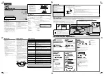
Serial interfaces
Connectors
The rear plate of the SRIO 500M unit contains
3 connectors for three serial interfaces:
Serial interface 1:
25- pin RS 232/current loop connector
Serial interface 2:
9- pin RS 485 connector
Serial interface 4:
25- pin RS 232/current loop connector
Figure 5. Connectors of the rear plate of the SRIO 500M unit.
Serial if
Serial if
Serial if
RS 232
RS 232
RS 485
1
13
12
24
25
37
36
48
4
2
1