


4
Connection
diagram
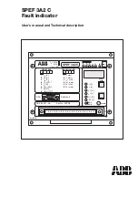
Fig 2. Connection diagram of the fault indicator.
Abbreviations of signal names
I
L1
, I
L2
, I
L3
Phase currents
I
0
Residual current
∆
I
Phase unbalance
SGF, SGB
Switchgroups for the selection of functions
ALARM
Alarm indicator
IRF
Internal fault
I> Alarm, I
0
Alarm and
Output relays
∆
I Alarm
I
load
(phase current),
Analog output signals
I
0
(residual current) and
∆
I (phase unbalance)
1
SGF 1/5
t
o
>
I
o
>
SPEF 3A2 C
∆
I>
t
&
&
SGF1/6
1
1
∆
HW
∑
IL1
IL2
IL3
X1-8
X1-9
X1-10
X1-1
1
X1-14
X1-15
X1-16
X2
X1-3
X1-2
X1-1
X1-17
X1-18
SGF 1/1
I
max
-I
min
I
max
>1s/ 80ms
SGF 1/3
>1s/ 80ms
SGF 1/2
X1-7
X1-12
X1-13
SGB /3
SGB /2
SGB /1
IRF
t>
SGF 1/4
1
>1s/ 80ms
I>
+
-
X1-6
24 Vdc
BLOCK_CO.FH3
IL1
IL3
IL2
+
-
SPEC 3
KOHU 24A1
Motor
drive
Disconnector
Control unit
SPOC 21XC
step &
program
Unbalance contact
(SPST
,NO)
Earth-fault contact
(SPST
,NO)
step &
program
ALARM
Reset
Io (analog out)
I (analog out)
Unbal. (analog out)
Common
Overcurrent contact
(SPST
,NO)
Common
Remote reset
input BS
Reset indicators, output relays and registers
Reset indicators and output relays
Reset indicators
Serial port
Filter
HW
step &
program
Filter
HW
Filter
HW
Can be used instead
of serial interface
load
load
load


