background image

Application according to designation, general safety instructions

6

Thermal Mass Flowmeter FMT400-VTS, FMT400-VTCS (Sensyflow VT-S/VT-CS)

42/14-36 EN

Notes and 
regulations 
to be 
observed

Observe
– the contents of these operating instructions and references to other documents and their contents
– the safety instructions attached to the mass flow meter
– the application data indicated in the calibration certificate
– the appropriate and valid safety instructions for the construction and operation of electrical systems
– the appropriate and valid safety instructions for handling gases
– the regulations and directives regarding explosion protection. 

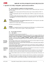
During 
operation

The operator must commission a qualified electrician to inspect and examine the system at defined intervals.
The examination intervals must be chosen in such a way that any damages that can be expected can be recog-
nised in time.
The examinations must be performed at least every three years.
The examinations can be skipped if the electrical system is continuously monitored by a responsible engineer.

Duties of the operator:
– maintain the system in proper condition
– continuously monitor the system
– execute required maintenance and repair work immediately
– carry out required safety measures.

If the devices are used in areas where dusts can cause explosion hazards, you must clean the devices
frequently. 

Use genuine spare parts, only.

2.2.2

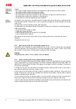
Notes concerning the use in potentially explosive areas

Only FMT400-VTS is available in a version authorized for use in zone 2 / zone 22. These devices come supplied
with an EU declaration of conformity (ATEX). For devices authorized for use in zone 2 / zone 22, only the data
and instructions for use stated in the declaration of conformity (ATEX) shall apply.

DANGER
Using the devices in zone 1 / 21 or in zone 0 / 20 is not allowed.

2.2.3

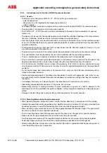
Notice according to the German Hazardous Material Directive

According to the German Waste Disposal Act dated 1986-08-27 (AbfG. §11 Special Waste) the owner of special
waste is responsible for its disposal. According to the German Hazardous Material Directive dated 1986-10-01
(GefStoffV, §17 General Protection Duties) the employer is also obliged to protect his employees. Therefore, we
must point out the following:

a) All flow sensors and/or flow transducers sent to ABB Automation Products GmbH for repair must be free of
any hazardous substances (acids, lyes, solutions, solids).

b) Flow sensors must be flushed and rinsed in order to neutralize hazardous substances. Flow sensors have
cavities. Therefore, the cavity must be neutralized after operation with hazardous materials (refer to German
Hazardous Material Directive, GefStoffV).

c) In case of service or repair, the measures listed in a) and b) must be confirmed in writing. This signed confir-
mation (return report) must be enclosed with the device whenever a device is returned to the factory.

d) Costs arising from increased efforts for handling of contaminated devices and the disposal of hazardous sub-
stances during repair shall be invoiced to the owner of the device!

!

Содержание Sensyflow FMT400-VTS

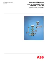
Страница 1: ...Operating instruction 42 14 36 EN Thermal Mass Flowmeter FMT400 VTS FMT400 VTCS Sensyflow VT S VT CS for gases compact configuration...

Страница 2: ...ducts GmbH Borsigstra e 2 63755 Alzenau GERMANY Tel 49 800 1114411 Fax 49 800 1114444 CCC support deapr de abb com Copyright 2006 by ABB Automation Products GmbH We reserve the right to technical amen...

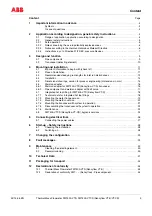
Страница 3: ...or process engineering dimensions in mm 15 4 6 Weld on adapter 16 4 6 1 Weld on adapter for FMT400 VTS Sensyflow VT S transducer 16 4 6 2 Pipe component and weld on adapter with ball valve 17 4 7 Inte...

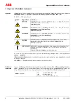
Страница 4: ...ice points or contact our technical user assistance hotline directly For all questions concerning the measuring system please have the calibration certificate readily at hand Symbol Signal Word Defini...

Страница 5: ...ertified and delivered in a safe condition To maintain this state and guarantee hazard free operation all safety instructions in this manual headed by DANGER WARNING CAUTION or NOTICE must be observed...

Страница 6: ...use in potentially explosive areas Only FMT400 VTS is available in a version authorized for use in zone 2 zone 22 These devices come supplied with an EU declaration of conformity ATEX For devices aut...

Страница 7: ...xious substances always rinse the pipes carefully When working on the pipes observe the applicable regulations for the prevention of accidents Do not use damaged pipe components or transducers Such un...

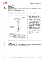
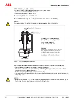
Страница 8: ...o the pipe Make sure that the sensor unit is not damaged Screw the transducer to the flange of the insertion pipe Evenly fasten the screws with the appropriate torque Torque for the screws supplied 87...

Страница 9: ...ects The measuring systems consist of only the 2 components detecting element and pipe component Fig 3 1 and Fig 3 2 show a schematic representation of the measuring systems FMT400 VTS process version...

Страница 10: ...er detecting element The detecting element which is designed as a plug in sensor contains apart from the sensor unit the completely cast transmitter switching unit installed in the connection head Thi...

Страница 11: ...ntion to the flow direction 4 Have the recommended input and output lengths been complied with 5 Is the installation between detecting element and pipe component correctly done 6 Are the used sealings...

Страница 12: ...pe lengths are used as steadying run lengths their length de pends on the type of the inlet run disturbance Recommended steadying lengths according to DIN EN ISO 5167 1 To achieve the stated measuring...

Страница 13: ...consult the DKD Calibration Department of ABB Automation Products GmbH at Alzenau An on site adjustment is also possible if reference flow values are precisely known by entering a calibration factor T...

Страница 14: ...the type 1 pipe component intermediate flange version with ball valve and a nominal width DN 200 ANSI 8 transducers with a length of 425 mm must be used 1 Centering pin 1 The flow direction must agre...

Страница 15: ...115 B4 58 269 263 28 5 115 600 486 DN 40 94 43 1 88 150 860 731 DN 50 109 54 5 102 165 1000 837 DN 80 144 82 5 138 DN 100 170 107 1 162 DN 150 226 159 3 218 450 DN 200 293 206 5 285 350 431 425 700 7...

Страница 16: ...erance 2 3 The centering pin of the adapter must be aligned in flow direction to the pipe axis at outlet run length behind measuring point 4 After welding the free passage for inserting the transducer...

Страница 17: ...ansducer and fasten it Prior to dismounting the transducer always check that the pipe is depressurized or that the pressure in the pipe is low enough to ensure safe dismounting Only then undo the 4 sc...

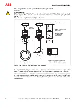
Страница 18: ...uring operation with virtually no gas escaping from the system It is recommended to use the hot tap fitting for measurements in main conduits e g compressed air systems or for measuring points which o...

Страница 19: ...ted hot tap fitting 4 7 2 Mounting the wafer flange version Fig 4 6 left shows the wafer flange version of the hot tap fitting mounted in the pipeline in disassembly position i e the guide tube is in...

Страница 20: ...d degree of shrinkage for welding The distance h from the upper edge of the flange on the fitting to the pipe central axis must be within a tolerance of 2 mm in measuring position Maintain the right a...

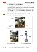
Страница 21: ...s to attach them to the special screws Fig 4 10 Rotate the Sensyflow transducer into measuring position using the lock nut Fig 4 10 The lower edge of the lock nut indicates the current position of the...

Страница 22: ...t ventilation is provided WARNING If when releasing the mounting screws you notice a large amount of gas escaping the activities must be stopped and screws retightened Check whether the fitting is act...

Страница 23: ...ransducers see chapter 4 7 5 To disassemble the guide tube release the 4 hex head screws on the lock nut Fig 4 8 and remove the guide tube Clean parts if necessary Replace the two internal Viton 36 x...

Страница 24: ...DN 25 DN 40 DN 50 DN 80 Standard measuring ranges 0 1 6 160 kg h 0 4 430 kg h 0 7 700 kg h 0 17 1700 kg h Standard measuring ranges 0 1 6 160 kg h 0 4 430 kg h 0 7 700 kg h 0 17 1700 kg h Standard me...

Страница 25: ...e transducers in the pipe components Select the gaskets in accordance with the connection standard used Pipe component hygienic version with FG flange FG 1 PN10 Transducer DN L L1 L2 D F 25 175 133 42...

Страница 26: ...ble e g 4 x 1 mm2 is required to connect the detector 2 Remove the connecting head cap of the detector by undoing the 4 screws 3 Connect the four wires to the terminal of the detector electronic unit...

Страница 27: ...tronics Connecting Connecting power supply 24 V Step Action 1 Check whether the voltage specified on the type plate matches the supply voltage 2 Use a power supply line with sufficient dimensions and...

Страница 28: ...ns voltage After power on the device is automatically on Step Check 1 Is the unit securely fastened 2 Are the electrical signal control and interface cable laid and connected correctly 3 Do the operat...

Страница 29: ...possible in case of fault The following settings will be possible in case of fault MIN 3 5 mA MAX 22 5 mA Notice The standard setting in case of fault is 0 20 mA for MAX and 4 20 mA for MIN These sett...

Страница 30: ...e under unfavorable conditions after transport under unfavorable conditions 1 Switch off the supply voltage 2 Remove the detector from the pipe component or weld on adapter make sure that the pipe is...

Страница 31: ...up to 3000 mm qmin qmax 0 1 6 160 0 4 430 0 7 700 0 17 1 700 0 30 3 000 0 80 8 000 0 130 13 000 0 27 000 2 700 000 qmin qmax 0 1 6 160 0 4 430 0 7 700 0 17 1 700 square ducts and larger diameters on...

Страница 32: ...dent on nominal size Material standard 1 4571 Ceramics stainless steel e g 1 4301 Process connection standard Flange acc to EN 1092 1 form B1 PN 40 or ANSI B 16 5 150 300 lbs Pipe fitting S acc to DIN...

Страница 33: ...absorbing material e g foam rubber The thickness of the shock absorber should be in accordance with the device weight and the type of shipment The box must be handled with care and has to be labeled...

Страница 34: ...34 Thermal Mass Flowmeter FMT400 VTS FMT400 VTCS Sensyflow VT S VT CS 42 14 36 EN 12 Declarations of conformity 12 1 Thermal Mass Flowmeter FMT400 VTS Sensyflow VT S 12 2 Declaration of conformity FM...

Страница 35: ...55 Alzenau Germany Tel 49 551 905 534 Fax 49 551 905 555 CCC support deapr de abb com ABB Inc 125 E County Line Road Warminster PA 18974 USA Tel 1 215 674 6000 Fax 1 215 674 7183 ABB has Sales Custome...

Отзывы: