ABB SCC-S Скачать руководство пользователя страница 23


 23 


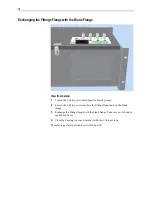
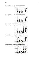
Replace Pressure Rollers and Springs 

Shut down the sample gas feed unit:


Stop the sample gas supply and shut off the sample gas feed unit power 

supply. 

Remove the hose:


Disconnect the external hoses from the hose connections. 

Using the handles, press the moving belt 

1

 together and turn the S-clip 

2

 as 

far as its limit stop. Remove the moving belt with hose from the pump head. 

Dismantle the pump head:


Unscrew the two screws 

3

 that secure the pump head. 

Pull the pump head 

4

 off the roller mounting axle, and remove the roller 

mounting 

5

 from the pump head. 

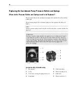
Replace pressure rollers and springs:


Press the pressure springs 

6

 slightly together and pull them out of the hole in 

the roller mounting 

5

 and out of the retaining slot in the roller axle 

7

Remove the roller axle from the roller mounting, and pull the pressure roller 

8

 off the roller axle. 

Before reassembling the hose pump, check all the parts for dirt and, if 
necessary, clean them with a dry cloth or oil-free compressed air. Do not use 
solvents for cleaning as they can attack the plastic parts. 

Push the new pressure roller 

8

 onto the roller axle 

7

 and secure with new 

pressure springs 

6

 in the roller mounting 

5

Fit the pump head:


Insert the roller mounting 

5

 in the pump head 

4

, and push both components 

together onto the roller mounting axle.  
During this process, check to ensure that the roller mounting axle and roller 
mounting fit together properly and that the flange on the rotating axis points 
towards the pump head front. 

10 

Secure the pump head 

4

 with the two screws 

3

Refit the hose:


11 

Insert moving belt 

1

 with the hose in the dovetail guides in the pump head. 

Using the handles, press the moving belt together while at the same time 
turning the S-clip 

2

 until it engages. 

12 

Connect the external hoses to the hose connections. 

Restart the sample gas feed unit:


13 

Switch on power supply to the sample gas feed unit. 

14 

The sample gas flow should only be restarted after the lead time period. 


Содержание SCC-S

Страница 1: ...SCC S Sample gas feed unit Operator s Manual 42 23 59 EN Rev 1 ...

Страница 2: ...nes 13 Connecting the Electrical Leads 14 Sample Gas Feed Unit Start Up 17 Power Supply and Sample Gas Activation 17 Sample Gas Pump Control 18 Peltier Cooler Control 19 Maintenance 20 Replacing the Condensate Pump Hose 20 Replacing the Condensate Pump Pressure Rollers and Springs 22 Replacing the Diaphragm and Valve Plates in the Diaphragm Pump 24 Checking Gas Path Seal Integrity 27 Troubleshooti...

Страница 3: ...e Parts OnLine You will find Parts OnLine on the Internet at http www abb com partsonline Service Contact If the information in this Operator s Manual does not cover a particular situation ABB after sales service will be pleased to provide further information Please contact your local service representative For emergencies please contact ABB Service Telephone 49 0 180 5 222580 Telefax 49 0 621 381...

Страница 4: ... Any other application is not compliant with the specified use Observation of this operator s manual is also part of the specified use The SCC S sample gas feed unit must not be used For feeding mixtures of gas air or gas oxygen that are capable of ignition during normal service For feeding flammable gas which may form an explosive mixture with air or oxygen and In a potentially explosive atmosphe...

Страница 5: ...lations standards and guidelines cited in this operator s manual are applicable in the Federal Republic of Germany The applicable national regulations should be followed when the device is used in other countries Device Safety and Safe Operation The device is designed and tested in accordance with the relevant safety standards and has been shipped ready for safe operation To maintain this conditio...

Страница 6: ...and connected to power should only be performed by trained personnel who are familiar with the risks involved When Safe Operation can no Longer be Assured If it is apparent that safe operation is no longer possible the device should be taken out of operation and secured against unauthorized use The possibility of safe operation is excluded If the device is visibly damaged If the device no longer o...

Страница 7: ... protected from Cold Heat sources such as the sun furnaces boilers Large temperature variations Strong blasts Accumulations of dust and dust infiltration Corrosive atmospheres Vibration Environmental Conditions Ambient temperature 10 to 40 C during operation 25 to 60 C during storage and transport Relative air humidity 75 year round average 95 on 30 days per year occasional light condensation perm...

Страница 8: ...tier cooler The sample gas dew point should be at least 5 C below the lowest ambient temperature throughout the sample gas path If this is not the case then a sample gas cooler unit or a condensate trap is required Version with Peltier Cooler max 50 C at max 25 C ambient temperature Scope of Delivery Scope of Delivery Quantity Description 1 SCC S Sample gas feed unit 1 Power supply cable length 2 ...

Страница 9: ...s 5 Flow monitor with needle valve Option second flow monitor for bypass 6 Peristaltic pump Option second peristaltic pump for external cooler 7 Membrane filter or condensate monitor 8 LED indicator for condensate alarm red 9 Pump switch 10 Temperature controller for cooler NOTE When mounting allow for the additional space required for the cooling air outlet on the left and right side of the unit ...

Страница 10: ...stigate damage assessment by the carrier rail post office forwarder within seven days Make sure that none of the enclosed accessories are lost during unpacking Keep the transport box and padding material for any future transportation which might be necessary C H A P T E R 3 Sample Gas Feed Unit Installation ...

Страница 11: ...urpose are screwed securely on the rear of the side panels in the factory To enable the cooling air to pass unobstructed into the unit to the rear the projection of the fixing brackets of approx 2 5 cm to the rear wall which is set up in the factory must not be reduced Sample Gas Feed Unit Installation in a 19 Inch Cabinet Rack If necessary remove the adhesive pads from the bottom If necessary ins...

Страница 12: ...en the housing cover 2 Loosen the 4 fixing screws each on the fittings flange and on the blank flange 3 Exchange the fittings flange with the blank flange Take care not to bend or squash any hoses 4 Close the housing cover and secure it with the 2 fixing screws The sample gas inlet port can be swiveled by 90 ...

Страница 13: ... from above Gas Connections The gas connections are PVDF or PPH fittings for DN 4 6 mm hose Gas Line Connection Connect the gas lines to the gas inlet and outlet fittings The gas lines should be made from material that is suited to the measuring task ...

Страница 14: ...as the mains voltage The protective conductor terminal must be connected to a protective conductor before any other connections are set up The device can be dangerous if the protective conductor is interrupted inside or outside the device or the protective conductor terminal is disconnected Use only fuses of the specified type and rated current as replacements Never use patched fuses The fuse hold...

Страница 15: ...e Test gas 1 6 Activation of solenoid valve Test gas 2 7 Internal power supply 0 V 8 Internal power supply 24 V DC Inside SCC S means The connection diagram shows the internal wiring of the sample gas feed unit The integrated power supply can also be used for the supply of external solenoid valves Terminal 7 0 V terminal 8 24 V maximum capacity 30 VA at 24 V DC Connect the signal lines recommendat...

Страница 16: ... a breaker in the power supply wiring near the sample gas feed unit This should allow the sample gas feed unit to be completely disconnected from the power supply if necessary The disconnection device should be easily accessible and identified in such a way that its relationship to the equipment that it is designed to disconnect can be clearly seen 4 Connect the delivered power supply cable to the...

Страница 17: ...e needle valve max 70 l h Version with Peltier Cooler 1 Activate the power supply 2 The condensate pump starts to run 3 The lead time is approx 10 minutes The flow alarm and the cooler temperature alarm are present during the lead time The condensate alarm may also be present 4 The lead time is finished and the sample gas feed unit is ready for operation when the sample gas outlet temperature of t...

Страница 18: ...ondensate alarm Alarm LED next to the Pump push button lights up red or a cooler temperature alarm K1 LED on the temperature controller is off is present The Pump push button continues to light up green After Power Failure The jumper JP1 located on the circuit board can be used to set whether the sample gas pump restarts automatically after a power failure Jumper in position 1 2 The sample gas pum...

Страница 19: ...w cooling Cooler overloaded 5 C Off pump off status alarm Lights up constantly yellow cooling 2 5 C Lights up yellow Off Ambient temperature too low 0 C Off pump off status alarm Off 1 if no condensate alarm is present and sample gas pump us switched on Pump push button lights up green See section Troubleshooting page 28 for further information on cooler problems Changing the Sample Gas Outlet Tem...

Страница 20: ...ginal pump hose as replacement part to ensure trouble free operation Never lubricate the condensate pump hose WARNING Residues from the condensate that the pump has been feeding may be found in the pump hose and the connected hoses These media can flow out when the hose connections are opened Take appropriate measures where needed to collect such residues The medium being fed may be corrosive and ...

Страница 21: ...should be replaced see section Replacing the Condensate Pump Pressure Rollers and Springs page 22 Fit a new hose 6 Before reassembling the hose pump check all the parts for dirt and if necessary clean them with a dry cloth or oil free compressed air Do not use solvents for cleaning as they can attack the plastic parts 7 Insert a new hose 3 with hose connections in the guides on the moving belt 1 8...

Страница 22: ...ee operation WARNING Residues from the condensate that the pump has been feeding may be found in the pump hose and the connected hoses These media can flow out when the hose connections are opened Take appropriate measures where needed to collect such residues The medium being fed may be corrosive and poisonous Appropriate precautions must be taken Wear protective goggles and protective clothing C...

Страница 23: ...ose pump check all the parts for dirt and if necessary clean them with a dry cloth or oil free compressed air Do not use solvents for cleaning as they can attack the plastic parts 8 Push the new pressure roller 8 onto the roller axle 7 and secure with new pressure springs 6 in the roller mounting 5 Fit the pump head 9 Insert the roller mounting 5 in the pump head 4 and push both components togethe...

Страница 24: ...eding may be found on the diaphragm and valve plates These materials can flow out when the diaphragm pump is opened Take appropriate measures where needed to collect such residues The medium being fed may be corrosive and poisonous Appropriate precautions must be taken Wear protective goggles and protective clothing Diaphragm Pump 1 Head cap 7 Valve plates 2 Head cap screws 8 Sealing rings 3 Space...

Страница 25: ... pump casing Replace diaphragm 8 Move the structural diaphragm 4 by rotating the fan impeller to its upper return point 9 Hold opposite sides of the structural diaphragm raise it then remove it by rotating in an anticlockwise direction Ensure that the cup spring 9 and the adjusting washer s 10 do not fall into the case from the threaded bolt of the structure diaphragm 10 Remove the cup spring 9 ad...

Страница 26: ...g gaskets 8 and head cover 1 on the case according to the markings 23 Check that the head cap is centered correctly by moving it gently sideways 24 Tighten the head cap screws 2 crosswise only slightly 25 Check that the pump moves freely by rotating the fan impeller 26 Move the structural diaphragm 4 by rotating the fan impeller to its upper return point 27 Hand tighten the head cap screws Reinsta...

Страница 27: ...d NOTE The feed unit must be checked from both sample gas connections because of the valves in the built in diaphragm pump Check for Leaks 1 Block off the sample gas outlet 2 Apply a positive pressure of 100 mbar to the sample gas inlet 3 Using a U pipe manometer for example pipe diameter 7 to 8 mm check the drop in pressure this must not exceed 0 1 mbar per minute 4 Similarly check for leaks from...

Страница 28: ...le gas line or modules blocked or closed Remove blockage or open modules Downstream modules blocked or closed Remove blockage or open modules Negative pressure on the gas sampling side Rectify negative pressure Sample gas flow insufficient flow alarm Positive pressure in the waste gas pipe Rectify positive pressure Cooler not working temperature indicator off Fuses blown Replace fuses Power supply...

Страница 29: ...are encountered during storage and transport Ambient temperature during storage and transport 25 to 60 C Shut Down the Sample Gas Feed Unit 1 Disconnect the power supply 2 Shut off the sample gas supply to the sample gas feed unit 3 Remove the gas pipes from the connections on the feed unit 4 Thoroughly purge the sample gas feed unit gas paths with an inert gas 5 Fully tighten the gas connections ...

Страница 30: ...ent material e g foam material The thickness of the cushioning material should be adequate for the weight of the device and the mode of shipping The box should also be lined with a double layer of bitumen paper for overseas shipping 3 Mark the box Fragile Handle with care Ambient temperature during storage and transport 25 to 60 C ATTENTION Before the sample gas feed unit is returned to the servic...

Страница 31: ...ample gas inlet for external infeed 6 Test gas inlet for external infeed 7 Condensate inlet from the external cooler 8 Condensate outlet Not supplied A External cooler B External multi way cock C External solenoid valves Option D Additional condensate pump for external cooler C H A P T E R 7 Annex ...

Страница 32: ...2 1 3 Version 2 Catalog number 23236 0 X21000XX0000 2 1 3 Version 3 Catalog number 23236 0 X31000XX0000 2 1 3 4 15 150 l h Version 4 Catalog number 23236 0 X22000XX0000 2 1 3 24VDC Version 5 Catalog number 23236 0 X32000XX0000 2 1 3 4 15 150 l h 24VDC ...

Страница 33: ...33 Version 6 Catalog number 23236 0 X2001XXX0000 1 3 8 8 7 D A 6 5 6 B Version 7 Catalog number 23236 0 X2101XXX0000 1 3 8 8 7 D A 2 Version 8 Catalog number 23236 0 X2201XXX0000 1 3 8 8 7 D A 2 24VDC ...

Страница 34: ...34 Version 9 Catalog number 23236 0 X2301XXX0000 1 3 8 8 7 D A 24VDC 2 2 Version 10 Catalog number 23236 0 X2011XXX0000 1 3 8 8 7 D A 24VDC 6 6 5 C ...

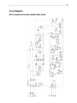
Страница 35: ...35 Circuit Diagrams SCC S Sample Gas Feed Unit without Peltier Cooler ...

Страница 36: ...36 SCC S Sample Gas Feed Unit with Peltier Cooler ...

Страница 37: ...37 SCC S Sample Gas Feed Unit 24 VDC Power Supply and Solenoid Valves ...

Страница 38: ...llation 7 R Replacing the Condensate Pump Hose 20 Replacing the Condensate Pump Pressure Rollers and Springs 22 Replacing the Diaphragm and Valve Plates in the Diaphragm Pump 24 Requirements for the Installation Site Power Supply 7 S Safety Information 4 Safety Instructions 5 Sample Gas Feed Unit Installation 10 Sample Gas Feed Unit Start Up 17 Sample Gas Inlet Conditions 8 Sample Gas Pump Control...

Страница 39: ......

Страница 40: ...inuous product improvement and the right is reserved to modify the information contained herein without notice Printed in the Fed Rep of Germany 10 11 ABB 2011 42 23 59 EN Rev 1 ABB Automation GmbH Analytical Stierstaedter Strasse 5 60488 Frankfurt am Main Germany Fax 49 69 7930 4566 E Mail cga de abb com 3KXG171203R4201 ...

Отзывы: