


35
17.2 VOLTAGE INDICATORS VDS
VDS is used to detect the presence or absence of medium
voltage according to IEC 61243-5.
The VDS are based on the HR system. The system consists
of a fixed device, installed in the switchgear, coupled with a
mobile device to visually detect the presence or absence of
service voltage and phase balance and on which the indicator
lights are installed.
The state of voltage present is visually indicated with at least
1Hz repetition frequency.
The „voltage indicators“ which are recommended are the
VIM1 type used as a mobile device and VIM3 type used as a
fixed and mobile device. Both are made by Maxeta.
The „voltage indicators“ have a maximum operating voltage
threshold of 90 V and a maximum current threshold of 2.5 uA
at 50Hz.
OPERATING TEMPERATURE
The VDS works reliably with a temperature range from –25°C
to +50°C.
PHASE COMPARATOR
The phase comparator detects the balance or unbalance of
the phases between the interface and/or the test points. De-
tection is by means of a luminous indicator.
The recommended phase comparator of the VDS is the PCM-
HR type, made by Maxeta. It consists of a 1.4 m long test
cable.
THRESHOLD VALUES FOR VOLTAGE INDICATION
When the line-earth voltage is between 45% and 120% of
rated voltage, indication of „voltage present“ must appear.
The „voltage present“ indication must not appear when the
line-earth voltage is less than 10% of the rated voltage.
17.3 VOLTAGE INDICATORS VDS LRM
With VDS LRM system, the following can be indicated:
-Overvoltage
-Nominal voltage presence
-Isolation problems
-No voltage
-Broken lead indication (Optional feature)
Indication is done visually on the display.
Contact the product manufacturer for detailed descriptions
and manuals.
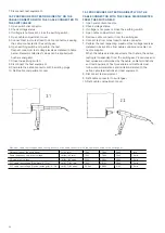
Phase sequence test
Capacitive voltage
indicator type HR
Содержание SafeRing
Страница 1: ...SafeRing SafePlus 12 24kV Installation and operating instructions Product manual...
Страница 43: ...43...