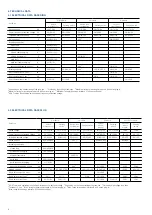
ABB SafeRing Скачать руководство пользователя страница 11

 11

Unit

A

B

C

1-way

NA

NA

NA

2-way

623

662

696

3-way

948

987

1021

4-way

1273

1312

1346

5-way

1598

1637

1671

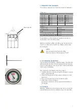
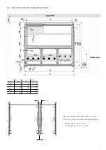
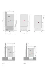
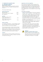
5.3 3-WAY SWITCHGEAR WITH BASE FRAME (AFLR)

Distance between two units which are connec-
ted to each other by means of external busbars

*) Top extension: 8 mm / 81 mm
    Side extension: 14 mm / 87 mm

indicates cable entry

81/87*

8/14*

Содержание SafeRing

Страница 1: ...SafeRing SafePlus 12 24kV Installation and operating instructions Product manual...

Страница 2: ...R 11 6 Dimensions 13 7 Internal arc classification IAC 14 8 Cable compartment 17 8 1 Standard cable compartment 17 8 2 Arc proof cable compartment 17 8 3 Cable connection 18 9 Extension of switchgear...

Страница 3: ...S LRM 35 18 Additional equipment 36 18 1 Low voltage connections 36 18 2 Remote control and monitoring unit 36 19 Cable testing 37 19 1 Procedure for switchgear with test points 37 19 2 Procedure for...

Страница 4: ...nformation shown in the manual by the following attention symbol After this symbol there are four different explanations indicat ing what types of injuries or damage can be caused should the recommend...

Страница 5: ...ed for installing the equipment Available modules are C Cable switch F Switch fuse disconnector D Direct cable connection De Direct cable connection with earthing V Vacuum circuit breaker Sl Busbar se...

Страница 6: ...m circuit breaker position Lower front cover 10 Nameplate of switchgear 11 Fuse blown indicator 12 Disconnector earthing switch position indicator 13 Capacitive voltage indication Cable compartment co...

Страница 7: ...to the supplier 3 2 STORAGE SafeRing SafePlus must be stored under cover in a dry and well ventilated area until it is installed and put into operation NOTE Use only approved slings when lifting Maxim...

Страница 8: ...is available with 42kV power frequency withstand voltage SafePlus C module F module V module V20 V25 module Switch disconnector Earthing switch Switch fuse combination Earthing switch Vacuum circuit...

Страница 9: ...umber of modules or units as appropriate The tolerance of the evenness is maximum 1 mm per meter Unit A B C 1 way 298 337 371 2 way 623 662 696 3 way 948 987 1021 4 way 1273 1312 1346 5 way 1598 1637...

Страница 10: ...10 5 2 3 WAY SWITCHGEAR WITH BASE FRAME AFL Unit A B C 1 way NA NA NA 2 way 623 662 696 3 way 948 987 1021 4 way 1272 1312 1346 5 way 1597 1637 1671...

Страница 11: ...21 4 way 1273 1312 1346 5 way 1598 1637 1671 5 3 3 WAY SWITCHGEAR WITH BASE FRAME AFLR Distance between two units which are connec ted to each other by means of external busbars Top extension 8 mm 81...

Страница 12: ...rame Dimensions for 290 mm baseframe Base frame height 450 mm Base frame height 290 mm Standard switchgear installed on cable trench Low version switchgear installed on cable trench 39 38 1786 1045 39...

Страница 13: ...02 2002 1230 1520 1680 Top connection with dead ends 1561 1851 2011 2002 2011 1325 1615 1775 External busbars 1591 1881 2041 2002 2041 1355 1645 1805 Busbar cover 1651 1941 2101 2002 2101 1415 1705 18...

Страница 14: ...entrance The energy produced by the internal arc causes the following phenomena Increase of the internal pressure Increase of the temperature Visual and acoustic effects Mechanical stresses on the sw...

Страница 15: ...t is freestanding i e distance from back of unit to wall exceeds 100 mm the area behind the unit must be restric ted and not accessible Arc shield Height of arc shield for M module is 1317 mm 1100 mm...

Страница 16: ...ternal Arc Classifi cation AFLR with ventilation upwards through exhaust channel the following must be considered Unit must be equipped with arc proof cable covers Unit can be installed as free standi...

Страница 17: ...val of cable cover 1 Lift handle to remove the cable cover pull out and lift cover up 2 Removal of front section 3 Front section removed 4 The mid panel can be removed by unscrewing Ax2 and B 8 CABLE...

Страница 18: ...ded ABB Kabeldon S dkabel Tyco Electronics Raychem Power Systems 3M Euromold NKT cables Please see supplier documentation for details DANGER The manufacturer s installation instructions must be follow...

Страница 19: ...VDD006006 GB 9 2 SIDE EXTENSION SafeRing and SafePlus can be equipped with a side extensi on See separate instruction manual 1VDD006106GB 10 CURRENT AND VOLTAGE TRANSFORMERS SafeRing and SafePlus can...

Страница 20: ...forbidden ABB Technology Ltd Edition 1 0 Document status RELEASED Responsible NODIS Title SafeRing SafePlus 12 24 Motor operation complete on 3PKSE mechanism for C Sl modules Language EN NO Location D...

Страница 21: ...hrough the center hole in the current transformer see figure on left and earthed on the earthing bar in the cable compartment A mounting plate for the current transformers is fitted in the cable compa...

Страница 22: ...r in the form of a manometer Additionally it is possible to fit a device for an electric signal if the pressure is low This requires auxiliary voltage supply 13 1 GAS PRESSURE SafeRing SafePlus contai...

Страница 23: ...structions 13 2 1 ADJUSTMENT OF GAS PRESSURE IN HIGHER ALTITUDES Remove the front cover in order to get access to the top of the manometer On top of the manometer a screw is situa ted Open this screw...

Страница 24: ...as pressure on the manometer should always be checked prior to operation Application of the X ray regulations One of the physical properties of vacuum insulation is the possibility of X ray emissions...

Страница 25: ...ry and control voltage on Carry out testing operations on switching devices either manually or using electrical control simultaneously obser ving the relative position indicators Check the mechanical...

Страница 26: ...s incorrect operation For detailed interlocking descrip tion see dedicated overview for each module in catalogue 1VDD006104 GB The operation of the switch disconnector circuit breaker and earthing swi...

Страница 27: ...rn the operating handle clockwise to charge the closing and the opening spring Close Push the green button A Open Push the red button B Switch disconnector Close Turn the operating handle clockwise Op...

Страница 28: ...of the charging lever The spring is fully charged when the indicator turns to charged spring yellow symbol about 10 operations needed to fully charge the spring CAUTION If the vacuum circuit breaker i...

Страница 29: ...15 4 OPERATION OF FUSE SWITCH DISCONNECTOR Switch fuse disconnector Charging springs Turn the operating handle clockwise to charge the closing and the opening spring Close Push the green button A Ope...

Страница 30: ...es reattach the fuse panel for easy detachment of safety wires 6 Pull out the fuse handle The fuses are firmly fixed in the fuse cover 7 Fix the fuses to the fuse cover using the contact screw This po...

Страница 31: ...SELECTION TABLE CEF The table is based on using fuses type ABB CEF Normal operating conditions with no overload Ambient temperature 25o C 40o C 120 Transformer rating kVA Fuse link rated voltage Un k...

Страница 32: ...1862M0002 20 10 10 10 10 16 16 20 20 25 40 40 20A 1YMB531012M0003 20A 1YMB531862M0003 22 10 10 10 10 16 16 20 20 20 40 40 40 25A 1YMB531012M0004 25A 1YMB531862M0004 24 10 10 10 10 16 16 16 20 20 25 40...

Страница 33: ...sing the key for the panel door 2 Use handles to lift door first up vertical then pull the door out horizontal 3 Remove plastic cover which is placed behind front door DANGER Always check voltage pres...

Страница 34: ...etition of at least 1 Hz NOTE Under very bright lighting it may be necessary to improve visibility by additional means OPERATING TEMPERATURE The VPIS will operate reliably over a temperature range of...

Страница 35: ...VDS works reliably with a temperature range from 25 C to 50 C PHASE COMPARATOR The phase comparator detects the balance or unbalance of the phases between the interface and or the test points De tecti...

Страница 36: ...A shunt trip coil AC or DC can be fitted on the transformer switch breaker 18 2 REMOTE CONTROL AND MONITORING UNIT SafeRing can be equipped with an integrated remote control and monitoring unit see p...

Страница 37: ...ber the following limitations DC and VLF voltages must not be applied to voltage transformers and surge arresters 19 1 PROCEDURE FOR SWITCHGEAR WITH TEST POINTS 1 Open switch disconnector 2 Check volt...

Страница 38: ...ve cable connector from the switchgear 6 Connect test rod or test lead to cable connector 7 Perform the test respecting maximum test voltage levels as detailed in instructions from cable supplier and...

Страница 39: ...r s instructions All components in the SF6 tank are maintenance free for the declared life expectancy of the product The tank is made of stainless steel 20 2 MAINTENANCE INTERVALS We recommend carryin...

Страница 40: ...rust from damaged paint work areas on steel sheet and other steel parts by mechanical means e g with a wire brush and apply appropriate anti corrosion treatment 20 5 REPAIRS NOTE If the switchgear is...

Страница 41: ...ation wrench 12 mm combination wrench 13 mm combination wrench X 14 mm combination wrench X 15 mm combination wrench 16 mm combination wrench 17 mm combination wrench 18 mm combination wrench 19 mm co...

Страница 42: ...n pallet 21 50 Yes Re use or use as energy additive in refuse incineration 21 2 RECYCLING CAPABILITY All figures are collected from CCF 3 way unit with fuse canisters 21 ENVIRONMENTAL CERTIFICATION 21...

Страница 43: ...43...

Страница 44: ...contact ABB AS Electrification Products division P O Box 108 Sentrum N 3701 Skien Norway Phone 47 35 58 20 00 www abb com Text and illustrations are not binding The right to make alterations is reserv...

Отзывы: