


An instance specific clear option is provided to delete all the through fault reports from local
HMI.
Through fault monitoring report handling
GUID-049E8C44-B981-4731-9882-0402AC57C17D v1
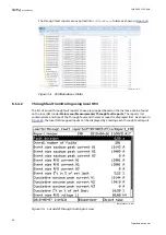
The through fault monitoring creates fault report for each through fault event. The through
fault information is stored in a zipped .xml file in the IED under flash/frep folder. Each instance
can have maximum 100 reports. Information in the through fault report is grouped into four
sections; the general section and other three sections containing individual winding and
phase-wise through fault data. The outputs given as ‘general data’ and ‘winding wise for all
phases’ in the through fault monitoring report are shown in
.
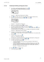
Table 2:
Through fault monitoring report outputs
General data
Winding wise for all phases
•
Test mode status
•
Fault duration in
seconds
•
Overall number of
faults
•
Event wise maximum
peak current W1
•
Event wise maximum
peak current W2
•
Event wise maximum
peak current W3
•
Event wise RMS
current W1
•
Event wise RMS
current W2
•
Event wise RMS
current W3
•
Event wise
I
2
t in % of
set limit
•
Cumulative maximum peak
current W1
•
Cumulative maximum peak
current W2
•
Cumulative maximum peak
current W3
•
Cumulative
I
2
t in % of set
limit
•
Event wise RMS voltage L1
(The winding is based on
the input connection to
U3P)
•
Event wise RMS voltage L2
(The winding is based on
the input connection to
U3P)
•
Event wise RMS voltage L3
(The winding is based on
the input connection to
U3P)
•
Multiple faults warning
•
Number of faults
•
Event wise maximum peak current
•
Event wise RMS current
•
Event wise
I
2
t
•
Event wise
I
2
t in % of set limit
•
Delta
I
2
t compared to prior fault
•
Cumulative maximum peak current
•
Cumulative
I
2
t
•
Cumulative
I
2
t in % of set limit
In case of 2-winding transformers:
•
The Winding 3 section is excluded from the report
•
The Winding 3 information under general section will have zero values
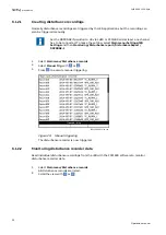
Each report is created with a unique identifier. For example, the second through fault report of
the first instance will have report identifier as
frep_1_2.zip
. The first digit in the identifier
indicates the instance number and the second digit represents the report number.
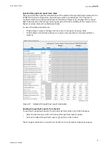
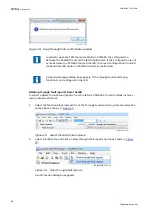
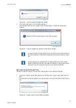
The through fault report can be read using the FTP client, PCM600 tool or via IEC61850 MMS
file transfer.
6.2
Resetting the IED
6.2.1
Clearing and acknowledging via the local HMI
GUID-9880CE57-79DE-4949-B9FA-1E91ED2F5F4B v5
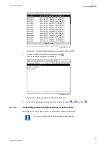
Use the Clear button to reset, acknowledge or clear all messages and indications, including
LEDs and latched outputs as well as registers and recordings. Pressing the Clear button
activates a view for selecting the reset function. Events and alarms assigned to alarm LEDs can
also be cleared with the Clear button.
1.
Press
to activate the Clear view.
1MRK 500 125-UEN A
Section 6
Operating procedures
41
Operation manual