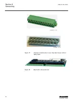
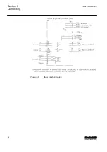
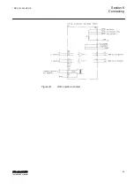


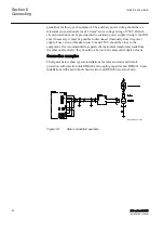


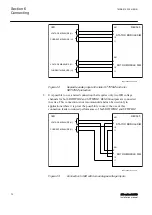
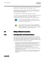
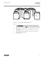
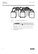


REX061 Capacitor unit connections
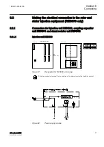
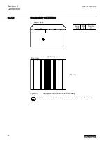
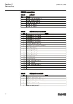
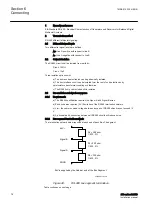
Table 16:
Injection and rotor connection X1
No
Signal
1
Rotor positive pole
2
-
3
Positive pole
4
-
5
Negative pole
6
-
7
Rotor negative pole
8
-
9
Rotor injection
10
Injection earth. Internally connected to chassis and PE
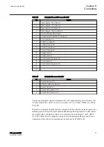
Table 17:
Measurment connector X2
No
Signal
1
Rotor + voltage divided by 1 000
2
Earth
3
Rotor - voltage divided by 1 000
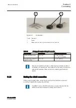
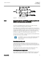
X1 connector. Connect each signal connector terminal of screw compression type
with one 0.14 to 6 mm
2
(AWG 35 - AWG 3) wire or with two 0.14 to 1.5 mm
2
(AWG 35 - AWG 15) wires.
X2 connector. Connect each signal connector terminal of screw compression type
with one 0.5 to 2.5 mm
2
(AWG 24 - AWG 14) wire or with two 0.5 to 1.0 mm
2
(AWG 24 - AWG 18) wires.
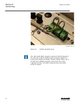
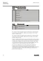
Protective conductor terminal must be connected to the cubicle or station protective
earthing system. Electrical codes and standards require that protective earth cables
are green/yellow conductors with a cross section area of at least 2.5 mm
2
(AWG
14). The cubicle must be properly connected to the station earthing system. Use a
conductor with a core cross section area of at least 4 mm
2
(AWG 12).
The protective earthing terminal is also the functional earth terminal. The
functional earth is the reference for rotor injection and measurement. The
connection to the generator earthing, and also to the station, should be as short and
low impedance as possible to reduce unwanted disturbances and improve the
quality of rotor measurements.
Section 6
1MRK 514 026-UEN B
Connecting
68
670 series 2.2 IEC
Installation manual
Содержание Relion 670 series
Страница 1: ...RELION 670 SERIES 670 series Version 2 2 IEC Installation manual ...
Страница 2: ......
Страница 10: ...4 ...
Страница 18: ...12 ...
Страница 24: ...18 ...
Страница 88: ...82 ...
Страница 100: ...94 ...
Страница 110: ...104 ...
Страница 111: ...105 ...


