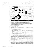
the opening of the breaker, which might cause unbalance conditions for which the
fuse failure might operate.
The output signal BLKZ will also be blocked if the internal dead line detection is
activated. The dead line detection signal has a 200 ms drop-out time delay.
The input signal MCBOP is supposed to be connected via a terminal binary input
to the N.C. auxiliary contact of the miniature circuit breaker protecting the VT
secondary circuit. The MCBOP signal sets the output signals BLKU and BLKZ in
order to block all the voltage related functions when the MCB is open independent
of the setting of
OpMode
selector. The additional drop-out timer of 150 ms
prolongs the presence of MCBOP signal to prevent the unwanted operation of
voltage dependent function due to non simultaneous closing of the main contacts of
the miniature circuit breaker.
The input signal DISCPOS is supposed to be connected via a terminal binary input
to the N.C. auxiliary contact of the line disconnector. The DISCPOS signal sets the
output signal BLKU in order to block the voltage related functions when the line
disconnector is open. The impedance protection function is not affected by the
position of the line disconnector since there will be no line currents that can cause
malfunction of the distance protection. If DISCPOS=0 it signifies that the line is
connected to the system and when the DISCPOS=1 it signifies that the line is
disconnected from the system and the block signal BLKU is generated.
The output BLKU can be used for blocking the voltage related measuring functions
(undervoltage protection, energizing check and so on) except for the impedance
protection.
The function output BLKZ shall be used for blocking the impedance protection
function.
11.2.7.2
Delta current and delta voltage detection
M13685-3 v7
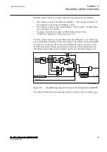
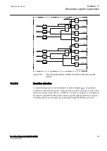
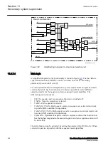
A simplified diagram for the functionality is found in figure
. The calculation of
the changes of currents and voltages is based on a sample analysis algorithm. The
calculated delta quantities are compared with their respective set values DI< and
DU>. The algorithm detects a fuse failure if a sufficient change in voltage without
a sufficient change in current is detected in each phase separately. The following
quantities are calculated in all three phases:
•
The change in voltage DU
•
The change in current DI
The internal
FuseFailDetDUDI
signal is activated if the following conditions are
fulfilled:
Section 11
1MRK 505 394-UEN A
Secondary system supervision
292
Line differential protection RED650 2.2 IEC
Technical manual
Содержание RED650
Страница 1: ...RELION 650 SERIES Line differential protection RED650 Version 2 2 Technical manual...
Страница 2: ......
Страница 36: ...30...
Страница 46: ...40...
Страница 232: ...226...
Страница 272: ...266...
Страница 288: ...282...
Страница 306: ...300...
Страница 406: ...400...
Страница 436: ...430...
Страница 502: ...496...
Страница 614: ...608...
Страница 628: ...622...
Страница 644: ...638...
Страница 760: ...754...
Страница 778: ...772...
Страница 814: ...808...
Страница 870: ...864...
Страница 874: ...868...
Страница 924: ...918...
Страница 925: ...919...

