1MRS750500-MUM
Feeder, Machine and Transformer Terminals
Operator’s Manual
RE_ 54_
17
5. HMI
Operation
Levels
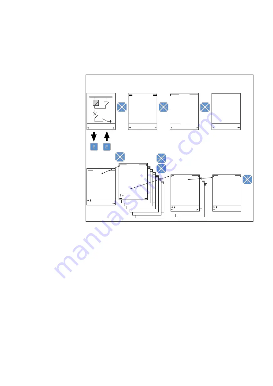
The HMI has two main levels: the user level and the technical level. The user level
is for measurements and monitoring, whereas the technical level is used for terminal
programming and parameterization.
menupict_b
Fig. 5.-1 HMI operation levels and their structure
21 kV
CB OK
Setting group 1
M EASUREMENT
EVENT view
ALARM view
USER LEVEL (LEVEL 1)
TECHNICAL LEVEL (LEVEL 2)
MIMIC view
MEASUREMENT view
EVENTS
N O C 3 L o w 3 1 / E 1
1 9 9 9 - 1 2 - 2 4
1 8 : 3 5 : 1 2 . 2 3 0
N O C 3 L o w 3 1 / E 1
1 9 9 9 - 1 2 - 2 4
1 8 : 3 5 : 1 2 . 3 3 0
N O C 3 H i g h 3 2 / E 1
1 9 9 9 - 1 2 - 2 4
1 4 : 2 5 : 5 2 . 7 2 0
N O C 3 H i g h 3 2 / E 3
1 9 9 9 - 1 2 - 2 4
1 4 : 2 5 : 5 2 . 7 6 0
E v e n t l i s t
M E A S
A L A R M
CB spring ready
SF6 gas density
Temperature
Interlocking
PARAMETER MENU
GROUP MENU
MAIN MENU
MAIN MENU
2 Sec
1 Sec
Protection
NOC3Low
SUBGROUP MENU
O p e r a t i o n m o d e
= D e f i n i t e t i m e
St a r t c u r r e n t
= 3 . 1 x I n
O p e r a t e t i m e
= 0 4 1 . 0 3 s
Ti m e m u l t i p l i e r
= 0 . 7 8
I E E E t i m e d i a l
= 0 . 5
C c l e a r s A L A R M s
E V E N T
M I M I C
U p d a t i n g v a l u e s
M I M I C E V E N T
A c t u a l s e t t i n g
S e t t i n g g r o u p 1
S e t t i n g g r o u p 2
C o n t r o l s e t t i n g
I n p u t d a t a
O u t p u t d a t a
R e c o r d e d d a t a 1
R e c o r d e d d a t a 2
R e c o r d e d d a t a 3
Status
Protection
Control
Cond. monit.
Measurement
Communication
General func.
Tests
Information
Configuration
CUB3Low_a
DEF2Low_a
DEF2High_a
DEF2Inst_a
Freq1_a
Freq2_a
Freq3_a
Freq4_a
Freq5_a
Inrush3_a
NEF1Low_a
NEF1High_a
NEF1Inst_a
NOC3Low_a
NOC3High_a
NOC3Inst_a
M I M I C v i e w
A L A R M M E A S
E M I M I C S u b m e n u
, M o v e c u r s o r
M a i n M e n u N e x t
, M o v e c u r s o r
P r e v . P a r a m .
, M o v e c u r s o r
P r e v . E S e t
, M o v e c u r s o r
I L 1 - A
0 0 2 5 0 . 0
I L 2 - A
0 0 2 5 2 . 0
I L 3 - A
0 0 2 4 9 . 0
I o - A
0 0 0 0 0 . 0
I o b - A
0 0 0 0 0 . 0
U o - V
0 0 0 0 0 0
U 1 - k V
0 2 0 . 0 0
U 2 - k V
0 2 0 . 0 0
U 3 - k V
0 2 0 . 0 0
f - H z
5 0 . 0 0
D e m a n d v a l u e s
I L 1 - A
0 0 2 4 8 . 0
I L 2 - A
0 0 2 5 1 . 0
I L 3 - A
0 0 2 5 0 . 0
P o w e r
P - k W
0 0 6 9 2 8
Содержание RE 54
Страница 1: ...Feeder Machine and Transformer Terminals RE_ 54_ Operator s Manual ...
Страница 2: ......


