background image

Operation Manual / Power2 340-H / Low-pressure stage

1 Introduction / 1.5 Layout and function of the low-pressure stage

© Copyright 2022 ABB. All rights reserved.

HZTL4053_EN

Rev.F

March 2022

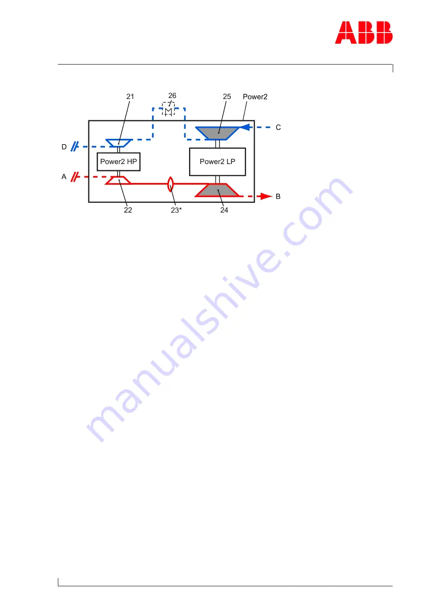
Mode of operation of the low-pressure stage (Power2 LP)

Fig. 3

Power2

Two-stage turbocharging

21

HP compressor

Power2 LP

Low-pressure stage

22

HP turbine

Power2 HP High-pressure stage

23*

Gas piping (bellows)

A

Exhaust gas inlet from internal combus-
tion engine

24

LP turbine

B

Exhaust gas outlet

25

LP compressor

C

Air or air/gas mixture inlet

26

Intercooler

D

Air or air/gas mixture outlet and supply
to the charge air cooler

- - -

Not included in the Turbo Systems
scope of delivery

*) If present

The low-pressure stage (Power2 LP) is a turbomachine and its main components are a tur-
bine and a compressor. These components are installed on a common shaft and form the ro-
tor 

 (see Fig. 2: 

8)

.

In the low-pressure stage (Power2 LP) shown in the sectional view 

 (see Fig. 2: 

8)

, the ex-

haust gas flows through the turbine casing (12) and the nozzle ring (11) and then reaches the
turbine (07). The turbine uses the energy contained in the exhaust gas to drive the rotor. The
exhaust gases then reach the atmosphere through the gas outlet flange (10), the gas outlet
casing (09) and the exhaust gas pipe connected to it.

The rotor runs in two radial plain bearings (06), which are located in the bearing casing (04)
between the compressor and turbine. The axial thrust bearing (05) is located between the
two radial plain bearings. The plain bearings are connected to a central lubricating oil duct
which is normally supplied by the lubricating oil circuit of the engine. The oil outlet always
lies at the deepest point of the bearing casing.

The compressor wheel (15) is also located on the rotor. The compressor wheel sucks in fresh
air or an air/gas mixture through the air suction branch (01) or filter silencer. In the com-
pressor wheel, the energy required for building up the pressure is transferred to the air or
air/gas mixture. As the air or air/gas mixture flows through the diffuser (03), the com-
pressor casing (02) and the intercooler (26), it is compressed further, cooled and then
guided into the HP compressor (21).

Page 

9

 / 

122

Содержание PT003924

Страница 1: ...al Product identification Serial number PT003924 Customer part number 1247658 Delivery date yyyy mm dd 2022 04 26 Weight 440 kg Operating limits according to rating plate Speed limit in test rig opera...

Страница 2: ......
Страница 3: ...ions 15 2 5 Intended use 16 2 6 Deflagration on gas engines 17 2 7 Warning plates on the low pressure stage 18 2 8 Rating plate of the low pressure stage 19 2 9 Periodic check of the pressure vessels...

Страница 4: ...nd gas outlet flange 70 9 5 Removing the air inlets 71 9 6 Measuring radial clearances N and R 72 9 7 Removing the compressor casing 73 9 8 Pressing off the casing 75 9 9 Removing the cartridge group...

Страница 5: ...98 12 1 REACH and RoHS Compliance Declaration For Products 98 12 2 Disposing of low pressure and high pressure stage components 99 13 Spare parts 100 13 1 Ordering spare parts 100 13 2 Spare part Illu...

Страница 6: ...prevention and environmental protection Target group The Operation Manual is aimed at engineers and trained mechanics responsible for the proper operation of the engine and for the Power2 connected to...

Страница 7: ...ressure stages This may result in sections and descriptions of components that are not relevant for a specific Power2 low pressure stage Please contact a Turbo Systems service station if you have any...

Страница 8: ...Operation Manual Power2 340 H Low pressure stage 1 Introduction 1 3 Essential information Copyright 2022 ABB All rights reserved HZTL4053_EN Rev F March 2022 Page 6 122...

Страница 9: ...LP and high pressure stage Power2 HP within two stage turbocharging Power2 The low pressure stage is always op erated in combination with a high pressure stage connected in series The two stage tur b...

Страница 10: ...2022 1 5 Layout and function of the low pressure stage Fig 2 01 Air suction branch filter silencer 09 Gas outlet casing 02 Compressor casing 10 Gas outlet flange 03 Diffuser 11 Nozzle ring 04 Bearing...

Страница 11: ...asing 12 and the nozzle ring 11 and then reaches the turbine 07 The turbine uses the energy contained in the exhaust gas to drive the rotor The exhaust gases then reach the atmosphere through the gas...

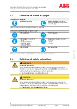
Страница 12: ...ment to be worn for a task The mandatory signs are described in chapter Safety and must be complied with Definition of Caution Warning Caution and warning signs are described in chapter Safety Terms u...

Страница 13: ...n over specified tightening angle Hand tight tighten without tools Oil Apply screw locking paste e g Loctite Apply high temperature grease Apply other paste in accordance with specifications Oil free...

Страница 14: ...rosion Inhibitor VCI WARNING Health protection when handling VCI VCI products are not hazardous in terms of the Ordinance on Hazardous Substances Nevertheless the following points must be observed whe...

Страница 15: ...group must be checked and repack aged by a Turbo Systems service station u Inspect the package for damage If the package is damaged the low pressure or high pressure stage or the cartridge group must...

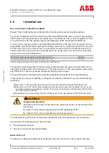
Страница 16: ...or supplies and materials Are a consequence of insufficient compliance with safety instructions Are a consequence of insufficient or inappropriate performance of maintenance and in spection work The o...

Страница 17: ...Respiratory mask to protect against Dusts Gases Safety helmet Ear protection Table 3 Personal protective equipment to be worn specific to the respective task 2 4 Definition of safety instructions WAR...

Страница 18: ...rating limits of Power2 were determined on the basis of information from the enginebuilder about the intended use This data is given on the rating plate and is gener ally different for the low pressur...

Страница 19: ...ar guideline value High pressure stages from Turbo Systems can tolerate a deflagration with a transient pres sure increase of 15 bar guideline value After a deflagration event Turbo Systems recommends...

Страница 20: ...ed locations or not readable proceed as fol lows u Order new warning plates from Turbo Systems service stations u Remove any warning plates that have become unreadable u Clean and degrease the areas d...

Страница 21: ...on Table 5 Operating limits Recommended inspection and replacement intervals 3 Inspection interval of plain bearings in 1000 h 4 Replacement interval of compressor in 1000 h 5 Replacement interval of...

Страница 22: ...ated values nBmax tBmax can considerably shorten the recommended replacement intervals In such cases Turbo Systems recommends contacting the nearest Turbo Systems service station nMmax tMmax normally...

Страница 23: ...ls The locally applicable legal regulations regarding periodic checks of the pressure vessels must be observed The operating company is responsible for the safe operation of the pressure vessel WARNIN...

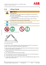
Страница 24: ...y helmet Fig 9 Attachment of loads on the crane hook Fig 10 Attachment angle If there are two or more suspension points the attachment angle of 45 must not be ex ceeded This prevents excessive loading...

Страница 25: ...st be checked periodically Suitable working materials and personal protective equipment must be kept in a perfect condition Only authorised personnel may remain in the vicinity of the Power2 when the...

Страница 26: ...r ear protection if the sound pressure level exceeds 85 dB A Wear ear protection Hazards due to hot surfaces Surfaces of the low pressure and high pressure stage attached parts and operating fluids lu...

Страница 27: ...sulation and for providing protection against contact with hot surfaces u Compliance with the instructions and specifications given by the en ginebuilder to protect against contact with hot surfaces o...

Страница 28: ...commissioning and operation u Visually inspect your working environment before starting work u Remove any obstacles and objects littering the workplace u Check all pipes to and from the Power2 for da...

Страница 29: ...otwear to protect against mechanical hazard and risk of fall ing Wear protective clothing WARNING Risk of falling When work is performed on the low pressure or high pressure stage there is a risk of f...

Страница 30: ...work Safety during disassembly assembly maintenance and repair u Observe the procedures for set up service and inspection work and the inspection inter vals u Inform the operating staff before starti...

Страница 31: ...ling vapours of operating materials and supplies or con tact with them may be harmful to health u Do not breathe in these substances and avoid contact with the skin u Ensure proper ventilation u Obser...

Страница 32: ...bres from insulation materials can have adverse effects on the health or cause irritations Unsuitable and combustible insulation materials are a fire hazard u Only use suitable and non combustible ins...

Страница 33: ...Fig 11 Transport Weight 440 kg Table 8 Weight of the low pressure stage complete 3 2 Removing the low pressure stage u Disconnect all pipes according to the instructions of the enginebuilder Version...

Страница 34: ...version of the bracket 04 a pin 03 may have been inserted to ensure the safe assembly of the low pressure stage Therefore always remove the low pressure stage from and install it on the bracket verti...

Страница 35: ...racket 01 The necessary sealing is provided by O rings The O rings are not included in the Turbo Sys tems scope of delivery Fig 13 Inserting gaskets into the bracket 01 Bracket 04 Slot for gasket 02 O...

Страница 36: ...ng gear to the suspension eye and additionally loop it around the gas out let casing 61001 3 Clean the contact surfaces of the fixing screws 01 in the bearing casing 4 Place the low pressure stage on...

Страница 37: ...htening torque 01 u If a support is present tighten the fixing screws 05 according to the following table Power2 Fixing screws 05 mm Tightening torques Nm 340 LP M16 180 Table 10 Fixing screw tighteni...

Страница 38: ...ly driven oil pump u Switch on the oil pump u Build up oil pressure Lubricating oil pressure 40 u Do not exceed a pre lubrication time of 2 minutes u Start the engine u Let the oil pump run until the...

Страница 39: ...tial commissioning phase and after all service work flush the complete lubricating system with warm oil u Use special running in filters when running in the engine and after all ser vice work on the l...

Страница 40: ...nginebuilder s instruc tions Wear safety gloves to protect against thermal hazards 4 2 4 Checks when starting up the engine u Measure speed oil pressure and charging pressure at various engine perform...

Страница 41: ...the exhaust gas pipe before and after the turbine for combustion residues or wa ter residues and clean it Remove any foreign objects that may be present u Check and clean filter silencer or air suppl...

Страница 42: ...es Fig 16 Oil monitoring 01 Contact surface of the low pressure stage 02 Oil inlet 03 Oil outlet M Oil pressure measuring point T Oil temperature measuring point If the drain pipe is vented the oil te...

Страница 43: ...e at the outlet The oil temperature at the outlet is mainly dependant on Lubricating oil temperature and pressure at the oil inlet Engine load and speeds of the low pressure and the high pressure stag...

Страница 44: ...ems enable the constant monitoring of the speeds of the low pres sure and the high pressure stage 5 3 2 Layout and overview Fig 17 Low pressure stage speed measurement system 86505 Speed sensor 42188...

Страница 45: ...difference is exceeded the following steps must be carried out u Reduce the engine performance immediately until the maximum speed of all low and high pressure stages no longer exceeds 70 of nBmax u I...

Страница 46: ...or from the speed sensor u Unscrew the defective speed sensor u Screw in new speed sensor to the stop u For the tightening torque of the low pressure stage speed sensor see document Operation Manual P...

Страница 47: ...es a maximum of 105 dB A near the compressor end compressor casing filter silencer air suction branch The following prerequisites must be fulfilled with regard to the low pressure and high pres sure s...

Страница 48: ...yright 2022 ABB All rights reserved HZTL4053_EN Rev F March 2022 Suggestion for noise insulation bellows Fig 18 Noise insulation bellows 01 Compressor casing 02 Bellows 03 Charge air duct scavenging a...

Страница 49: ...vir onmental conditions poor fuel quality or high system vibrations can lead to untimely machine damage even if the prescribed service intervals are ob served u Agree on a specific service interval wi...

Страница 50: ...nozzle ring turbine casing and compressor casing and check for cracks and erosion corrosion 6 2 5 Entries in the engine logbook The monitoring of the engine enables conclusions to be drawn on the beh...

Страница 51: ...must be made between the intervals to be expected for replacing the bearing parts and replacing the non rotating components exposed to hot gas A decisive role is played by various influencing paramet...

Страница 52: ...lity and fuel treatment Load profile thermal cycling also number of starts stops emergency shutdowns Gas inlet temperature Frequency and execution of turbine and compressor cleaning Specification of t...

Страница 53: ...on Duration of post lub rication min Oil pressure during post lubrication en gine stopped poil bar 550 imperative 15 20 0 5 poil 1 0 550 necessary until the ro tor comes to a stand still 10 recommende...

Страница 54: ...be maintained Recommended cleaning inter val Operating state LP HP compressor 24 72 h Engine load 50 85 LP filter silencer 500 h Engine stopped HP bellows At every disassembly Engine stopped Table 17...

Страница 55: ...purity of the sucked in air Deposits can form in the flow channels if salt oil mist or dust are sucked in with the air Consequences of contamination Impaired compressor efficiency Higher exhaust gas...

Страница 56: ...ocess is particularly suitable as long as the fouling is not too ad vanced 7 2 3 Prerequisites for wet cleaning of compressor Engine load of 50 85 CAUTION Volume of water Uncontrolled volumes of water...

Страница 57: ...leaning of compressor Executing wet cleaning u Remove sealing plug 27005 u Fill container with 0 4 dm3 pure water u Screw in sealing plug 27005 again u Push the valve activator 03 against the spring a...

Страница 58: ...lter ring 81265 u Remove the filter ring u Clean the filter ring as required or every 500 hours of operation and replace it after the fifth cleaning process at the latest Contamination of the filter r...

Страница 59: ...on segments may only be cleaned lightly with pres surized air a soft brush or a moist cleaning cloth u Have any heavily contaminated absorption segment replaced by a Turbo Systems service station Fitt...

Страница 60: ...ssure stage Rotor unbalance Contact a Turbo Systems service sta tion Turbine or compressor damaged Bearing damaged Table 20 Malfunctions when starting Vibrations Rubbing of rotating parts Normal behav...

Страница 61: ...Turbo Systems service sta tion Change of operating state of high pressure stage Check the operating point of the high pressure stage Pipes Defects such as leaks in the ex haust gas pipes or charge ai...

Страница 62: ...ure too high Engine performance and engine speed unchanged Possible causes Remedy Engine Malfunction in the injection system Repair or contact manufacturer Low pressure or high pressure stage Insuffic...

Страница 63: ...er silencer contaminated there fore pressure drop too high Clean Compressor turbine contaminated Compressor turbine damaged Contact a Turbo Systems service sta tion Exhaust gas back pressure too high...

Страница 64: ...he compressor wheel compressor blade breakage Possible causes Remedy Low pressure or high pressure stage Material of the compressor wheel corroded due to the influx of ventila tion gases containing co...

Страница 65: ...ng If the low pressure or high pressure stages surge continuously or periodic ally their components may be damaged u Gradually reduce the engine load u Have the cause clarified and remedied immediatel...

Страница 66: ...e stage contaminated Clean Bearing damaged Contact a Turbo Systems service sta tion Rotor rubbing Foreign object in the pressure stage Table 34 Malfunctions when stopping Runout noises Runout time too...

Страница 67: ...ensor 86505 refer to chapter Ordering spare parts Replace the speed sensor Table 36 Speed measurement poor signal amplitude Measured speed too high Possible causes Remedy Low pres sure or high pres su...

Страница 68: ...ied out only by trained personnel from a Turbo Sys tems service station u Mark the casing position for assembly Tightening torques for components The specified bolted connection tightening torques mus...

Страница 69: ...on of the assembly devices Not all assembly devices are marked with a part number Identification is guaranteed by the tool list This list is enclosed with the toolbox WARNING Servicing the assembly de...

Страница 70: ...rights reserved HZTL4053_EN Rev F March 2022 Swivel lifting eyes to be used Swivel lifting eyes are required for the safe lifting of loads which are not supplied by Turbo Systems Fig 20 Swivel liftin...

Страница 71: ...ies are rounded up standard values Fig 21 Weights of the assemblies Designation Weight kg 01 Filter silencer 40 02 Radial air suction branch 13 03 Axial air suction branch 6 04 Compressor casing 65 05...

Страница 72: ...et casing 61001 with lifting gear 2 Remove screw 61003 with Verbus Ripp washer 61004 and support 61300 3 Loosen nuts 51009 and remove with Verbus Ripp washers 51004 4 Remove the gas outlet casing 6100...

Страница 73: ...ving the air inlets u Mark the casing position for assembly Fig 23 Removing the air inlets 1 Attach lifting gear to the filter silencer 81000 or air suction branch 82000 2 Loosen and remove V clamp 72...

Страница 74: ...earance and measure simultaneously at the top N1 and the bottom N2 2 Calculate clearance N and compare it with the permissible values in the table 3 Push the feeler gauges 01 into the gap without clea...

Страница 75: ...remove together with fastening strips 72012 2 Attach swivel lifting eye S to the compressor casing and the lifting gear 3 Remove the compressor casing 72000 and turn it 180 4 Remove and dispose of the...

Страница 76: ...L4053_EN Rev F March 2022 Dismantling the wall insert Fig 26 Dismantling the wall insert 1 Knock the wall insert 77000 out of the compressor casing 72000 with a plastic tip hammer 2 Attach swivel lift...

Страница 77: ...9 8 Pressing off the casing CAUTION Axial force of the press off tool Using the press off tool 90042 a high level of axial force can be generated If the casing is pressed off with too much force on o...

Страница 78: ...assembly Do not remove oil orifice if present To limit the oil flow rate through the bearing casing during operation engine under load to the admissible values an oil orifice is mandatory at the oil...

Страница 79: ...s Ripp washers 51003 together with fastening strips 51002 Fig 30 Removing cartridge group 2 3 Insert screws from service support into cartridge group 4 Secure ring nuts VRM onto the screws with washer...

Страница 80: ...Rev F March 2022 9 10 Removing the nozzle ring Fig 31 Removing the nozzle ring 1 If present Remove the metal C ring 51105 2 Position the fastening strips 51002 in place 3 Pull out the nozzle ring 5600...

Страница 81: ...022 ABB All rights reserved HZTL4053_EN Rev F March 2022 9 11 Installing the cartridge group on the service support Fig 32 Installing the cartridge group on the service support 1 Remove ring nuts VRM...

Страница 82: ...Table 43 Permissible clearances A and B 1 Move the rotor to and fro up to the stop In order to obtain a correct measurement elev ate the turbine a little 2 Measure clearance A and compare it with the...

Страница 83: ...st be clamped between the heat shield 42400 and the turbine casing 51000 Fig 34 Nozzle ring compression PD 42001 Bearing casing 51000 Turbine casing 42400 Heat shield 56001 Nozzle ring Product Nozzle...

Страница 84: ...ng 56005 in the correct slot see detail A1 A2 When doing this pay attention to correct winding of the lamellar sealing ring see detail B 2 Secure the lamellar sealing ring 56005 with adhesive tape 01...

Страница 85: ...g the cartridge group and rotating it by 90 Fig 36 Lifting the cartridge group and rotating it by 90 1 Loosen and remove nuts 2 Lift the cartridge group out of the service support 90012 3 Insert the s...

Страница 86: ...e group Product Size Tightening torque Nm Power2 340 H LP M12 75 Table 45 Tightening torque 51007 1 Coat the threads of the studs 51006 with high temperature grease 2 Align the casing position of the...

Страница 87: ...lling the compressor casing Fitting the wall insert and the diffuser Fig 38 Fitting the wall insert and the diffuser Product Size Tightening torque Nm Power2 340 H LP M6 8 Table 46 Tightening torque 7...

Страница 88: ...graphite cord sealing 42126 is fitted instead of the O ring 42012 see Spare parts 100 Product Size Tightening torque Nm Power2 340 H LP M12 105 Table 47 Tightening torque 72011 1 Fit a new high tempe...

Страница 89: ...learance and measure simultaneously at the top N1 and the bottom N2 2 Calculate clearance N and compare it with the permissible values in the table 3 Push the feeler gauges 01 into the gap without cle...

Страница 90: ...ts Fig 41 Installing the air inlets Product Size Tightening torque Nm Power2 340 H LP M12 60 Table 49 Tightening torque 72020 1 Secure lifting gear to filter silencer 81000 2 Fit a new O ring 81010 to...

Страница 91: ...HZTL4053_EN Rev F March 2022 9 19 Installing the gas outlet flange Fig 42 Installing the gas outlet flange 1 If present Insert the metal C ring 57003 into the turbine casing 51000 and secure with high...

Страница 92: ...LP 51009 M12 65 Nm Power2 340 LP 61003 M20 320 Nm Table 50 Tightening torques 51009 61003 1 Insert a new gasket 61002 into the gas outlet casing 61001 2 Coat thread of studs with high temperature gre...

Страница 93: ...44 Tightening torque overview The following tightening torques Nm must be observed for the designated screw fittings Position Part number Tightening torque Nm 01 82005 82007 M18x1 5 60 02 72020 M12 6...

Страница 94: ...in an environmentally compatible manner Wear safety gloves to protect against thermal hazards CAUTION Directives for taking out of operation Serious damage to engine or property can be caused by non c...

Страница 95: ...ys have repairs to the cartridge group carried out by a Turbo Sys tems service station NOTICE Quick recommissioning To enable you to put a defective low pressure or high pressure stage back into opera...

Страница 96: ...turbine casing into the gas pipe and on the gas outlet casing again u Attach cover plate Fig 45 Fitting the cover plate u Make sure that the oil connections in the bracket are equipped with gaskets 1...

Страница 97: ...te drawing The cover plate is not included in the Turbo Systems scope of delivery and must be manufac tured by the operating company according to the following drawing Material General structural stee...

Страница 98: ...e largely protected against corrosion Preparations for mothballing WARNING Handling operating materials and supplies Swallowing or inhaling vapours of operating materials and supplies or con tact with...

Страница 99: ...pressure and high pressure stage are completely removed either as whole units or in single parts For the measures always necessary for preparing the low pressure and high pressure stage for mothballi...

Страница 100: ...m the customer of the presence of such substance s with sufficient information available to the supplier RoHS2 Directive 2011 65 EC in English only The EU Directive 2011 65 EC recast restricts the use...

Страница 101: ...ngine oil electronic parts speed sensor and associated components and thermal insulation u Dispose of metals as scrap metal for recycling u Dispose of non metallic materials as waste u Dispose of resi...

Страница 102: ...rts can be ordered from an Turbo Systems Service Station u If different model variants are not taken into account in this document contact an Turbo Systems Service Station u Dispose of placed and unus...

Страница 103: ...re part Illustrations The spare parts lists shown below are only available in English Cartridge oil cooled 42196 42197 10900 42189 42188 42012 HZTL443580 Mod A Available within the spare part set if p...

Страница 104: ...eserved HZTL4053_EN Rev F March 2022 Cartridge water cooled 42196 42197 10900 42189 42188 42012 HZTL443581 Mod A Available within the spare part set if provided Part no Designation 10900 Cartridge wat...

Страница 105: ...32103 32104 32111 32110 32101 32109 32113 42002 HZTL443579 Mod A Available within the spare part set Part no Designation 21000 Turbine 21002 Piston ring 25000 Compressor wheel 32101 Radial bearing 32...

Страница 106: ...v F March 2022 Bearing casing oil cooled 42196 42197 42400 42001 42305 42008 42301 42302 HZTL443367 Mod A if provided Available within the spare part set Part no Designation 42001 Bearing casing 42008...

Страница 107: ...2001 42189 42140 42188 42141 42305 42142 42008 42301 42302 HZTL443296 Mod B if provided Available within the spare part set Part no Designation 42001 Bearing casing 42008 Socket screw 42140 Gasket 421...

Страница 108: ...1003 51007 56005 56001 51102 51101 51102 51101 HZTL443297 Mod A p pre assembled Part no Designation 51000 Turbine casing 51002 Fastening strip 51003 Verbusripp washer 51006 Stud 51007 Hexagon nut 5100...

Страница 109: ...ll rights reserved HZTL4053_EN Rev F March 2022 Gas outlet casing 61004 61003 61005 61300 61001 61002 HZTL443298 Mod A Available within the spare part set Part no Designation 61001 Gas outlet casing 6...

Страница 110: ...77005 72011 72012 79000 72005 79041 79040 77000 72000 72080 72020 72080 HZTL443299 Mod A Available within the spare part set Part no Designation 72000 Compressor casing 72005 Screw plug 72011 Hexagon...

Страница 111: ...ABB All rights reserved HZTL4053_EN Rev F March 2022 Air suction branch axial 82000 82007 82008 82010 82006 82005 HZTL443013 Mod D Available within the spare part set Part no Designation 82000 Air su...

Страница 112: ...ABB All rights reserved HZTL4053_EN Rev F March 2022 Air suction branch radial 82005 82006 82010 82000 82008 82007 HZTL443012 Mod D Available within the spare part set Part no Designation 82000 Air s...

Страница 113: ...6 81270 81000 82006 81137 82005 81135 81171 81170 81271 81266 HZTL443011 Mod E Available within the spare part set Part no Designation 81000 Filter silencer complete 81010 O ring 81135 Silencer body 8...

Страница 114: ...Illustrations Copyright 2022 ABB All rights reserved HZTL4053_EN Rev F March 2022 Speed measurement system 86526 86505 86528 86517 HZTL443427 Mod A if provided Part no Designation 86505 Speed sensor...

Страница 115: ...er tool set 90000 is required Part number Designation Quantity 90012 Service support 1 90013 Plastic insert 1 90042 Press off tool 1 90070 Extraction device 2 Table 67 Customer tool set 90000 This too...

Страница 116: ...bellows e g dents cracks scratches or weld spatters All criteria mentioned also apply to the C ring gaskets Moreover they must not exhibit any buckling Checks after commissioning engine in idle mode...

Страница 117: ...rval The following maintenance work must be carried out on the gas piping u If present Remove insulation u Perform a visual inspection for cracks and deposits Always replace bellows with cracks with a...

Страница 118: ...2022 15 3 Removal and installation 15 3 1 Weight Product Weight kg Gas piping Power2 340 H 11 Table 70 Weight 15 3 2 Removing gas piping Only use textile lifting gear to lift the bellows Fig 47 Remov...

Страница 119: ...ar to lift the bellows Fig 48 Installing the bellows u Coat threads of all screws with high temperature grease u Position bellows 85001 with metal C rings 61007 85002 u Fit screws 85003 and nuts 85004...

Страница 120: ...erial and Disposal 98 15 5 Spare parts 15 5 1 Ordering spare parts Please quote the following data when making queries and ordering spare parts Serial number of Power2 HT Serial number of the low or h...

Страница 121: ...Low pressure stage 15 Gas piping option 15 5 Spare parts Copyright 2022 ABB All rights reserved HZTL4053_EN Rev F March 2022 15 5 2 View of gas piping with part numbers Fig 49 Gas piping with part num...

Страница 122: ...s out let flange 70 Fig 23 Removing the air inlets 71 Fig 24 Measuring clearances N and R 72 Fig 25 Removing the compressor casing 73 Fig 26 Dismantling the wall insert 74 Fig 27 Press off the casing...

Страница 123: ...Power2 HP speed reductions 59 Table 25 Malfunctions during operation Power2 LP speed increases 59 Table 26 Malfunctions during operation Power2 HP speed increases 60 Table 27 Malfunctions during oper...

Страница 124: ...spare part set 97070 100 Table 55 101 Table 56 102 Table 57 103 Table 58 104 Table 59 105 Table 60 106 Table 61 107 Table 62 108 Table 63 109 Table 64 110 Table 65 111 Table 66 112 Table 67 Customer...

Отзывы: