23
PQSTOR I
I N S TR U C TI O N M A N UA L
Perform the following commissioning procedure
after the first installation of your product.
5.1 Installation check
WARNING:
Before checking the installation, make
sure that the module is isolated from the
electrical network. In systems of multiple
modules connected in parallel, ensure that each
module is disconnected from the power supply.
•
Make sure that the module is installed in a
location where no conductive dust is present
and that it conforms to tolerable altitude,
temperature and environmental conditions
(Table 13). If these limits are exceeded, see
Section 5.5 on derating the system
•
Ensure that adequate upstream electrical
protection is provided
•
Check the product for visible damage
(e.g. from transport)
•
Check that the installation fulfills requirements
set out in Section 4, notably:
- Check the tightness of connections,
including power cables, grounding, battery
connections, optional CT connections and
RJ12 CAN bus communication connectors, as
well as connection terminals of the blackstart
board, if used (see Section 4.5)
- Check the cross-section of cables
(Section 4.5).
WARNING:
Before powering the PQstorI make
sure that it is not mechanically or electrically
damaged and that it can tolerate the voltage on
the electrical network.
Close the upstream protection for powering the
module. If the cabling is correct, the red status
LED on the front panel of the module ( in Figure
2) will turn on.
Log onto the Wi-Fi user interface (Section 3.1.1).
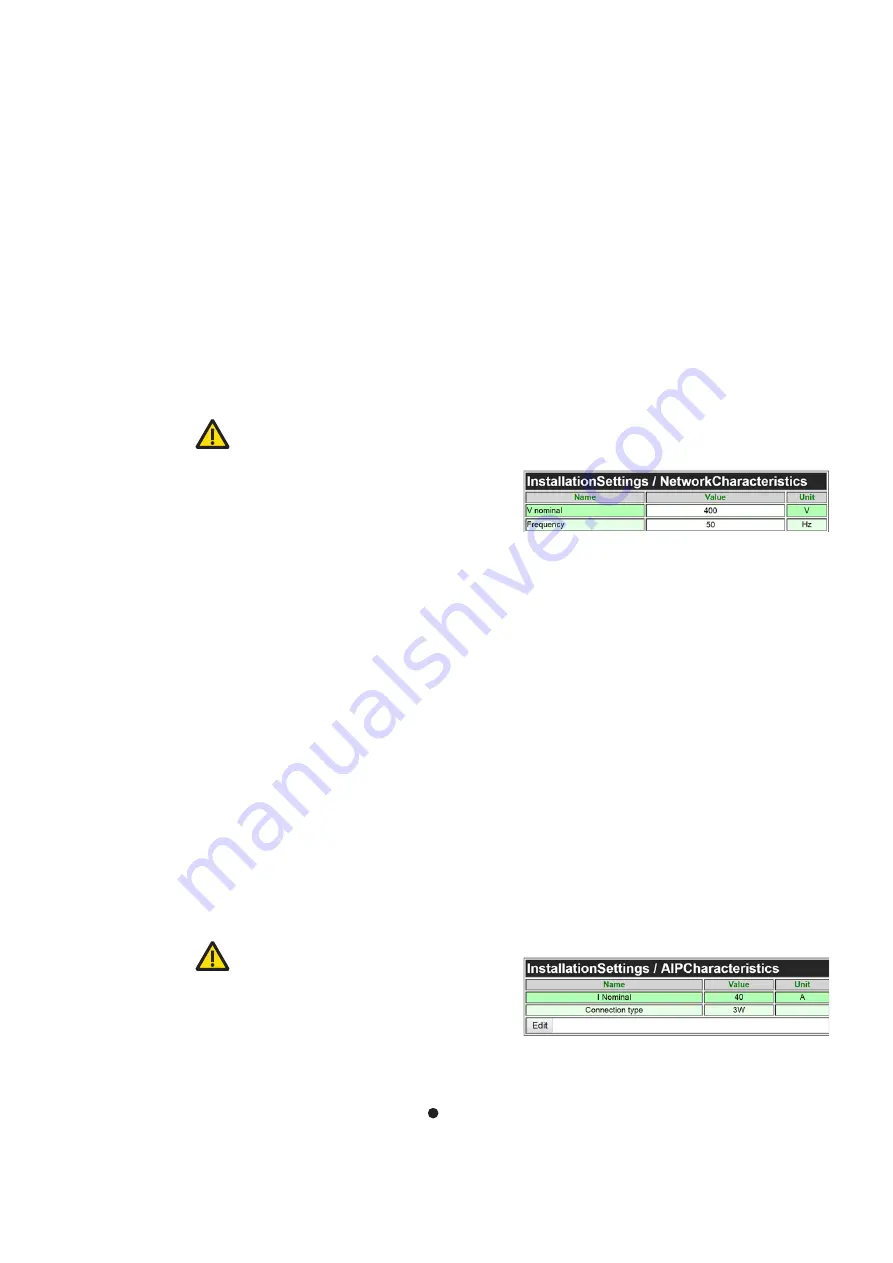
5.2 Network characteristics
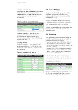
Navigate to the
Network Characteristics
page of
the Wi-Fi user interface (Section 3.6.1) and set the
nominal network voltage
and
network frequency
of the electrical network (Figure 20).
The inverter is suitable to operate with a voltage
+/-10% of nominal voltage, +/-7% of nominal
frequency, without grid code compliance.
In case of requirement to comply with any local
grid code, please contact ABB.
5.3 AIP characteristics
Navigate to the
AIP Characteristics
page (Section
3.6.2) of the Wi-Fi user interface and enter the
connection mode of the system as either 3-wire
(only phase lines are connected) or 4-wire
(neutral is also connected). The 4w operation is a
feature that still is not available for normal use in
the inverter. Modules are rated in terms of their
current at 400 V (i.e. a 30 kW rated module
corresponds to 40 A, 80 kW to 120 A and the
100 kW to 150 A respectively).
5.4 CT settings (optional)
—
Figure 20: Configuring PQstorI network characteristics
—
Figure 21: Configuring PQstorI characteristics
—
05 Commissioning
5


