18
PQSTOR I
I N S TR U C TI O N M A N UA L
3.9.4 Battery monitoring
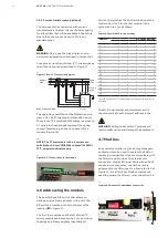
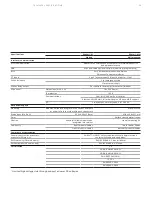
Table 11 lists Modbus commands to monitor the energy storage system operated by the PQstorI. These
function are detailed further in Section 3.7.3.
—
NOTE: For grid code related parameters, please refer to the PQstorI Grid Code Functionality Manual
and PQstorI Modbus table.
3.9.5 PQstorI commands
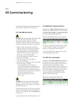
Table 12 lists Modbus commands to operate the PQstorI. These functions are described in further detail
in Section 3.5.5.
—
Table 11: Modbus commands to monitor the state of the battery
—
Table 12: Modbus commands for operating the PQstorI
Name
Address
Unit
Type
Register
length
Range
Description
Min.
Max.
Battery
Voltage
36203
V
Float
2
-3200
3200
DC voltage (V) on DC output of
inverter (= Battery voltage)
Battery
Current
36205
A
Float
2
-3200
3200
DC current (A) on DC output of one
unit inverter (= Battery current),
positive when discharging
the battery
Udc (Inverter
DC voltage)
30523
V
Float
2
0
3200
The DC voltage present on
the inverter DC bus
Name
Address
Unit
Type
Register
length
Range
Description
Min.
Max.
Start request
44611
-
Word
1
0
1
Must be set (1) to start unit,
provided no error is
currently present
Stop request
44612
-
Word
1
0
1
Must be set (1) to stop the unit or
prevent if from restarting as soon
as the error has disappeared
Reset fault
44613
-
Word
1
0
1
Must be set (1) to acknowledge the
fault that has caused the unit stop
Set P
46201
kW
Float
2
-3200
3200
Active power (kW) to be
injected into the grid (when in
current source mode). Positive
target means discharging
Set Q
46203
kvar
Float
2
-3200
3200
Reactive power (kvar) to be
injected into the grid
(when positive, inverter
behaves like a capacitor)
Heart beat
timeout
46229
-
Word
1
0
0xFFFF
Heart beat signal: Once modbus
client has set it to non-zero value,
it must change it every 20 seconds
at least otherwise the inverter
will stop and generate a
heartbeat fault. By default
heartbeat is not active


