14
NAL/NALF – Mounting and operation manual
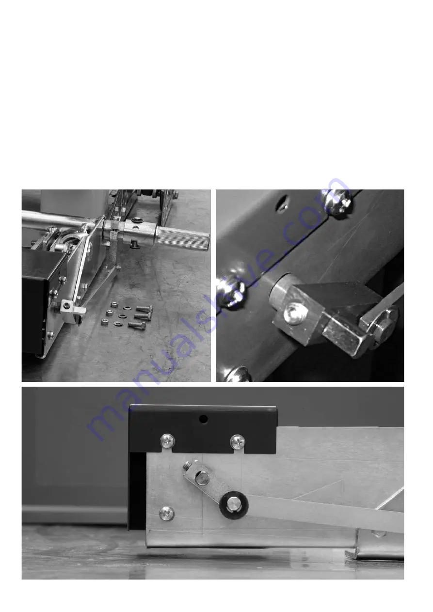
11.0 Mounting the auxiliary switch for E-EB earthing switch,
excluding LCES, Fig. 40-50.
1. The installation starts with the earthing switch in open position,
see Fig. 40.
2. The arm of auxiliary switch should be at an angle 45-50 degre-
es in direction of earthing switch, see Fig. 41.
3. Holdfast screw must be tightened from the flat side of auxiliary
switch shaft, see Fig. 42.
Fig. 40
Fig. 42
Fig. 41
Fig. 40-42 Mounting the auxiliary switch for E-EB earthing switch


