10
MDO16GNS October 2005 – Issue 2
Triguard
SC300E
D
C
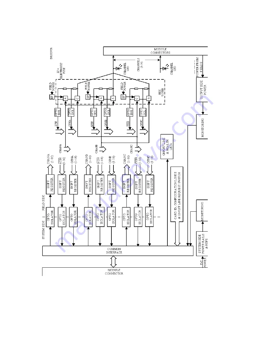
Figure 2-4. MDO16GNS – Block Diagram
Страница 1: ...e state of all channels the circuit on line status and the health of the module The module which is compatible with dual slot hot repair can be fitted in any of the ten I O slots in the SC300E chassis Wrong slotting is prevented by physical coding The SC300E main processor software identifies the module via a built in hardware identifier Channel outputs leave the module via the DIN 41612 rear plug...
Страница 2: ...2 MDO16GNS October 2005 Issue 2 Triguard SC300E ...
Страница 3: ...16 Channel D O Module 48Vdc Mechanical coding block Upper ConfigurationLinks Link3 ICC B H L V HW GTZ Figure 1 1 General view and front panel detail 321 320 Link 1 Connector J1 Common Interface CI Module Connector J2 Connector J3 Mechanical coding block Lower ...
Страница 4: ...ion in module 4W Module power consumption including field power dissipation in module 6W minimum load 36W maximum load Overall size mm Overall size inches 400 9U H x 397L x 28W 15 75H x 15 63L x 1 1W Weight 2 1kg ENVIRONMENTAL SPECIFICATIONS The maximum ambient temperature measured at the hottest point within the Triguard system shall not be greater than 60 degrees centigrade Temperature operating...
Страница 5: ...ober 2005 Issue 2 5 Triguard SC300E MDO16GNS 16 Channel D O Module 48Vdc TRANSPORT AND HANDLING The MDO16GNS must be transported and stored in its original packing material which should be retained for this purpose ...
Страница 6: ...ry installed in a pattern determined by the module and corresponding set screws are removed from the chassis coder blocks to enable fitting Unused holes are plugged with set screws The chassis slot coder block configuration for this module is shown in Figure 2 1 Figure 2 1 Chassis slot coder blocks configuration EXTERNAL CONNECTIONS Field Circuits The field load circuit shown in Figure 2 2 is the ...
Страница 7: ...ot shown All the digital outputs are routed through connector J2 In the external connection diagram Figure 2 3 the following symbols are used 0 First mate long pin x Connector pin Earth Connected to chassis ve Field supply in ve Field supply return O P Channel output WARNING J3 pin 1c is connected to earth All other pins on J3 are connected to field supply return but this field supply return may n...
Страница 8: ... 2 4 each path is controlled by its own microcontroller in the common interface In order to minimise the number of data connections across the 1kV system to field barrier the channel data are converted to serial form before entering the module from the common interface In this manner 16 output channels can be served by just three paths instead of 48 The three data streams are each applied to opto ...
Страница 9: ...rn to switch its output alone to the opposite state and confirm the correct operation of its individual output switch The module power requirements are served from two different sources The power for the output side circuits is derived from the chassis 12V supply via dc dc converters All of the supplies are monitored Electronic fuse circuits sense the current in each output path and cut off the up...
Страница 10: ...10 MDO16GNS October 2005 Issue 2 Triguard SC300E D C Figure 2 4 MDO16GNS Block Diagram ...
Страница 11: ...ics on line off line status and signal status read write cycles to and from the SC300E processors via an I O communications bus All I O modules have an identification code which is read by the common interface and passed to the main processors for verification The on line off line status is determined by the main processors If for maintenance purposes the On Off Line Request switch on the front of...
Страница 12: ...12 MDO16GNS October 2005 Issue 2 Triguard SC300E Figure 2 5 Common interface Block diagram ...
Страница 13: ...is In the case of an Input Output fault the Health LED on the faulty module will be extinguished PREPARATION To ascertain whether the chassis I O slot containing the faulty module has been allocated a hot repair partner use one of the following methods Check the system drawings Check the chassis wiring configuration Use the I O chassis Configuration Report on the TriBuild workstation Where there i...
Страница 14: ...2 Triguard SC300E When inserting a module ensure that it is aligned with the markings on the chassis rails and that it engages with the top and bottom guides Improper insertion may cause damage to the module and or chassis connectors ...
Страница 15: ...LEDs do not illuminate either the first or second time or fail to remain illuminated then the module must be considered faulty DUAL SLOT HOT REPAIR 1 Insert the new module into the vacant hot repair slot ensuring that it engages properly in the upper and lower guides in the chassis The top and bottom chassis rails carry alignment marks to assist Pull out the ejection levers and as the module is pu...
Страница 16: ...16 MDO16GNS October 2005 Issue 2 Triguard SC300E SERVICE SUPPORT SPARES Spare parts and technical advice can be obtained from your local area offices ...