Balancing
The motors rotor is dynamically balanced.
As standard, balancing has been carried out using half
key, and the shaft is marked with a RED tape, with the
text Balanced with half key. To avoid vibration, the
coupling-half or pulley must be balanced with a half key
after the keyway has been machined.
When balancing with full key, the shaft is marked with a
YELLOW tape, with the text Balanced with full key. To
avoid vibration, the coupling-half or pulley must be
balanced without a key after the keyway has been
machined.
In case of balancing without key, the shaft is marked
with a BLUE tape, with the text Balanced without key.
Special instructions for motors with a
frequency converter
ABB motors with protection types EEx d, EEx de, EEx e
(on request) and Ex nA/Ex N or EEx nA are certified for
use in variable speed drives.
The use of a motor with a frequency converter must be
studied in advance. Check that the motor fulfils the
specifications. The maximum loadability (T = f(N)) of the
motor and the type or characteristics of the converter
are shown by an additional rating plate or by a test
report delivered with the motor.
Flameproof motors EEx d(e) operating with a frequency
converter must be fitted with passive thermal protection
(thermistors, PT100). For non-sparking motors Ex nA/
Ex N or EEx nA such protection is recommended. The
converter must be capable of processing this informa-
tion.
Bearing currents with frequency converter
drives
The operation of a frequency converter induces addi-
tional high frequency shaft voltages, which can cause
sparking and high frequency current flow through the
motor bearings.
The motor cable must be symmetric and shielded. The
motor must be grounded and connected according to
the manual Grounding and cabling of the drive system.
The shield must be connected to both motor frame and
the inverter PE-terminal.
Bearing voltages and currents (sparks) must be avoided
in all Ex-motors. To prevent sparking and high fre-
quency bearing current flow inside the motor, a properly
dimensioned filter at the converter output is highly
recommended when nominal voltage is higher than
600V. Insulated bearings are fitted as listed below:
Sizes 280-400
Insulated bearing in the N-end (non-drive end).
The insulation method is indicated on the motor rating
plate, e.g. INSULATED BEARING IN N-END.
Connection
In frequency converter applications, motor frame exter-
nal earthing must be used for equalising the potential
between the motor frame and the driven machine,
unless the two machines are mounted on the same
metallic base. See manual Grounding and cabling of
the drive system.
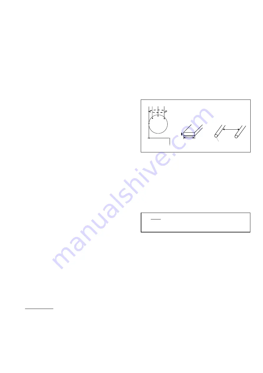
For motor frame sizes above IEC 280, use 0.75 x 70
mm flat conductor or at least 2 x 50 mm² round conduc-
tors. The distance of the round conductors must be at
least 150 mm from each other.
When the motor and the gearbox are mounted on a
common steel fundament, no potential equalisation is
needed.
To comply with EMC-requirements, use cables and
connectors approved for this purpose. (See instruction
for frequency converters).
NOTE: The oscillating frequencies of common mode
currents are very high, from 10 kHz to 1 MHz depending
on the actual drive set-up. Therefore, special attention
should be paid to the hf-impedance of the potential
equalising lead. A flat wound copper conductor or flat
copper bar is strongly recommended. The conductor
length should be as short as possible.
Note
For motors with a nominal voltage above 600 V,
du/dt filter or sinusoidal filter must be used.
Potential equalization
U1
V1
W1
PE
3 ~ M
Driven machinery
0.75 mm
70 mm
> 150 mm
min 50 mm
Cables/wires
Plate/strip
Содержание M2A series
Страница 2: ...2 LV Motors Ex motors instructions 00 11...


