ABB KM26 Скачать руководство пользователя страница 11

11

KM26 | 

MAGNETIC LEVEL GAUGE  |  OI/KM26-EN REV I
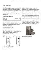
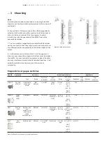
Floats

The float is a strong capsule that is engineered for the 
temperature and pressure conditions of an application and 
designed to be precisely buoyant in a liquid or liquids 
(interface). The float follows the surface of the process fluid 
or liquid-liquid interface as the level in the chamber 
fluctuates. The float interacts magnetically with a visual 
indicator mounted on the outside of the chamber to reveal 
the liquid level inside. Communicating the fluid level 
information using the float’s magnetic field isolates the level 
indicator from the process allowing for longer lasting, error-
free operation of the KM26 MLG.

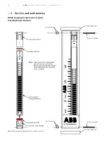
The float (figure 11) is a key component of the KM26 MLG and 
is engineered to match the medium in respect of density, 
pressure resistance and material durability. Every float is 
precisely engineered to customer application, ensuring 
optimal accuracy and performance. Precisely spaced magnets 
create a 360° magnetic field coverage, safeguarding level 
transmitter and gauge performance, even the most 
challenging applications. Several materials of construction 
available including titanium, Monel®, Hastelloy® C, stainless 
steel, and plastics. Tefzel®, Halar®, TEFLON® S protective 
coatings are also available. The float is equipped with a ring 
system of permanent magnets for transmission of liquid level 
to the indicator. The indicator is linked magnetically to the 
magnet system in the float. During installation, it may be 
necessary to remove the float from the chamber. For proper 
operation, the float must be reinstalled using the proper 
orientation. Floats may be marked with ‘top for SPM’ or floats 
may be marked with an arrow indicating the proper 
orientation.

KM26S float is shipped inside the chamber unless specified 
for separate shipment. Most floats are labeled to indicate the 
top of the float, the specific gravity of the fluid and the serial 
number of the chamber for which they are designed. If the 
float is coated, labeling is not performed and the float should 
stay with the chamber. The top of the float can be found by 
locating the magnet placement and direction with respect to 
the indicator in the scale. The indicator should be attracted to 
the float, not repelled, when inserted correctly.

The KM26T float is wrapped separately in bubble wrap. The 
magnet assembly at the end of the float rod is inserted into 
the top of the guide chamber unless the float rod is too long, 
in which case it will be shipped outside of the guide chamber. 
The stop tube and disk are installed over the rod end and into 
the chamber. Then, the snap ring is inserted into the internal 
groove to hold the assembly in place. Finally, the float is 
threaded onto the rod and locked in place with the nut 
provided.

 . . . 3     Mounting

Figure 11 - KM26 MLG floats

If specific gravity decreases, the float will have more of its 
length below the fluid level and give a visual indication that is 
lower than actually exists. If the fluid specific gravity has 
significantly changed after the unit has been placed in 
service, it may be necessary to replace the float in order to 
allow for accurate level indication. This can change the length 
and magnet position of the float. The stop springs must be 
adjusted accordingly. On the KM26S this is accomplished by 
either stretching or compressing (or cutting) the bottom and 
top springs. The scale may also have to be adjusted to 
coincide with the floats’ new zero position. To adjust the zero 
for the KM26T, the float stop tube can be elongated or 
reduced.

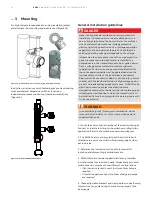
The chamber must be vertically level (plumb) to insure proper 
operation of the float and its follower. A unit that is not 
leveled properly may decouple unexpectedly due to friction 
with the sides or because the float travels too far away from 
the indicator.

Do not weld on MLG or on the vessel with indicator and 
float installed, this will damage the magnetic circuit.

CAUTION

The end user must provide adequate structural support 
for the chamber in the field. It is recommended that, for 
longer chambers (and especially for non-metallic 
constructions), support brackets attached to the side of 
the level gauge are placed at minimum intervals of 6 feet.

NOTICE

Float Stop Springs

Springs are often included in the top and bottom of a the 
MLG chamber.  The primary purpose is to provide protection 
for the float during operation and shipping/handling. If 
pressure rapidly enters the chamber (possibly due to a quickly 
opened valve), the float could be propelled toward the top of 
the chamber at a high rate of speed.  The spring will dampen 
the impact and assist in protecting the float from damage.

Содержание KM26

Страница 1: ...e free solution for total and or interface level detection in toxic corrosive high pressure and high temperature processes ABB offers the standard KM26 magnetic level gauge with a chamber of virtually any non magnetic material extruded process connections a custom engineered float and all accessories with 316 stainless steel construction ABB also offers a dual chamber redundant level system which ...

Страница 2: ...nts 1 Introduction 2 2 Safety 4 3 Mounting 9 4 Troubleshooting 21 5 Service and maintenance 21 6 MLG parts 28 7 MLG parts ordering 30 8 Customer specific product information 30 9 Certificate EU declaration of conformity 30 10 Warranty 31 11 RMA form 32 ...

Страница 3: ...in the float chamber is a float which is designed to float with approximately 70 to 80 of its mass submerged in the process fluid The float magnet assembly is located such that the magnetic actuation point of the magnet assembly is at the liquid level when the fluid is at the specific gravity specified The position of the float will vary directly with the level of the process fluid The indicator a...

Страница 4: ... installation electrical connection commissioning and maintenance of the KM26 series MLG Qualified personnel are those individuals who have experience in the installation electrical connection commissioning and operation of the KM26 series MLG or similar devices systems and hold the necessary qualifications These qualifications include but are not limited to training or instruction authorization t...

Страница 5: ...al packaging or other suitably secure shipping method The sender should contact the factory for return authorization number and fill out return form provided at the end of the manual and include it with the device According to C guidelines other local laws for hazardous materials the owner of the corresponding hazardous waste is responsible for its disposal The owner must observe the proper regula...

Страница 6: ...g the equipment include but are not limited to limited mechanical agitation shall be used use of stilling wells to mitigate effect of agitation limit rate of change of level to values such that friction sparks cannot occur less than 1 m s at all times extra precaution should be taken during installation and maintenance to prevent float from traveling down up chamber too fast while initially fillin...

Страница 7: ...ottom or lower chamber branch connection locations For the KM26S it is also acceptable to connect a wire ring terminal to a flange stud locked in with another nut The grounding connection must be metal to metal so any paint must be sanded off Refer to figure 4 for possible grounding locations Example grounding hardware is depicted below Figure 3 ATEX only nameplate Figure 4 Ground hardware Figure ...

Страница 8: ...perature classifications of the ATEX approved KM26 is limited to process temperatures up to 50C below the maximum surface temperature allowed for each of the temperature classes as per the below table ATEX constructional marking II 2 G c TX external II 1 G c TX internal Applicable standards EN134653 1 2009 EN13463 5 2001 Pressure equipment directive PED 97 23 CE Based on the order the product shal...

Страница 9: ...thin 24 hours Do not discard the shipping container until all parts components are verified and checked 3 Mounting General Read the following installation instructions carefully before proceeding Failure to observe the warnings and instructions may cause a malfunction or personal hazard Before installing the KM26 ensure the device design meets the requirements of the measurement point from both a ...

Страница 10: ...le flange at the bottom and a cap at the top A float assembly hangs below the chamber into the liquid via a guide rod The float assembly consists of a magnet at the top of a guide rod and a float at the bottom As the float itself does not contain any magnet in this configuration this is also used in applications where the liquid contains magnetic particles A stilling well can also be used within t...

Страница 11: ...tracted to the float not repelled when inserted correctly The KM26T float is wrapped separately in bubble wrap The magnet assembly at the end of the float rod is inserted into the top of the guide chamber unless the float rod is too long in which case it will be shipped outside of the guide chamber The stop tube and disk are installed over the rod end and into the chamber Then the snap ring is ins...

Страница 12: ... delivered correctly set up for measuring the product specified in the order The optional magnetic bar graph indicator is available in yellow black or red white for use in locations where temperature is not excessive The flippers on the bar graph rotate to change color at the fluid level The indicator tube is positioned such that the normal downward travel of the float is stopped at a position tha...

Страница 13: ...sition on the chamber figure 14 Limit switches To signal specific liquid levels the KM26 can be equipped with several different types of ABB limit switches Magnetically actuated limit switches are the most commonly used devices They can be clamped to the measuring chamber and are adjustable over the entire measuring range They are actuated by a magnet incorporated into the float The process operat...

Страница 14: ...elements overvoltage protection devices lightning protection and or voltage separation capacity must be provided at the plant Check that the existing operating voltage corresponds to the voltage indicated on the name plate In case the surge protection option is present and the transmitter is installed in a hazardous area the transmitter has to be supplied power from a voltage source isolated from ...

Страница 15: ...ctions gussets support brackets etc may interfere with installation at desired locations Cam actuated switches must be mounted in the correct orientation Magnetic level gague switches Model Approvals Enclosure Switching mechanism Application Type Rating Electrical connection Type contacts Rating Min max process temp Deadband High temp Vibration High corrosion LMS100 FM FMC ATEX IEC Hermetically se...

Страница 16: ...uring length of the gauge align the zero mark with the zero of the scale if the transmitter measuring length matches the center to center of the gauge align the zero mark with the center of the bottom process connection 7 mark the MLG chamber where the mounting tabs of the transmitter match up to the chamber Also place a mark on the MLG chamber that corresponds to the mounting tabs of any support ...

Страница 17: ...itter reads higher than zero raise the transmitter If the transmitter reads lower than zero lower the transmitter 16 Attach proper field wiring to the transmitter according to the instruction manual included with the transmitter 17 Open the process to the MLG using the procedure included in the isolation valves section Installation with insulation pad If the transmitter includes an insulation pad ...

Страница 18: ...ssary to retain the tube in the channel 3 Cryogenic indicator tubes are sealed into the scale assembly and should be replaced as a unit These scale assemblies are strapped in place using gear clamps Vent and Drain The vent and drain connections provide the user an alternate way to pipe into the chamber In many cases the drain is left either plugged or closed off with a valve It can be opened at an...

Страница 19: ...y the scale is located opposite to the process connections and the insulation will be thinned down to in on that side If the scale has been moved from the position that it is shipped in then the thinned insulation will not be in the correct location When ordering ABB refers to location by a clock system with the process connections at 12 o clock when looking down on the unit from above The scale i...

Страница 20: ...e to identify the true liquid level because of the very abnormal performance Similarly if a large number of small bubbles form underneath and around the float it will decrease the buoyant force that is keeping the float on the surface This could cause the float to submerge completely in the liquid To combat this phenomenon a oversize chamber with guide rod design can be incorporated into the chamb...

Страница 21: ...of the tank vessel 4 Troubleshooting Indicator decoupling Causes float is upside down Remove check field strength of magnets and install correctly Proximity to opposing field may weaken magnetic field scale assembly is not flat against the chamber due to missing straps Magnetic field strength drops exponentially with distance Add gear clamps to eliminate channel separation from chamber Add stainle...

Страница 22: ...ugh the chamber top end 2 After cleaning the MLG chamber replace the float and drain flange A new flange gasket may be required 3 Note Use gaskets compatible with process fluid 4 Verify that the stainless steel pipe gear clamps are tight and ensure that the scale assembly has the positive zero in the correct location relative to the chamber and float 5 Use a permanent magnet or KTEK magnet tool to...

Страница 23: ...6 Align top tube holder with scale channel and slide down until top surface of the holder is flush with top of scale channel The screw hole should align with the hole in the holder 7 Use a 6 32 machine screw to lock top tube holder in place 8 Tighten nut and install a second nut to lock tube holders in place 5 Service and maintenance KM26 magnetic bargraph glass installation procedure refer to fig...

Страница 24: ...24 KM26 MAGNETIC LEVEL GAUGE OI KM26 EN REV I 5 Service and maintenance Figure 27 KM26 shuttle replacement glass installation procedure KM26 shuttle replacement glass installation procedure ...

Страница 25: ...holder cavity 4 Carefully align replacement glass with shuttle indicator into scale channel and lower into bottom tube holder Ensure glass tube rest flat on rubber bumper and is firmly seated Nipple on bottom end of glass tube should protrude through slot in rubber bumper 5 Place rubber bumper on top of glass tube 6 Align top tube holder with scale channel and slide down until top surface of holde...

Страница 26: ...26 KM26 MAGNETIC LEVEL GAUGE OI KM26 EN REV I 5 Service and maintenance KM26 bargraph replacement glass installation procedure Figure 29 KM26 bargraph replacement glass installation procedure ...

Страница 27: ...r into bottom tube holder Flat faces on glass tube should register with corresponding flat faces in cavity of bottom tube holder Ensure glass tube rest flat on rubber bumper and it firmly seated Nipple on bottom end glass of glass tube should protrude through slot in rubber bumper 5 Place one 1 rubber bumper on top of glass tube 6 Align top tube holder with scale channel and slide down until top s...

Страница 28: ...Scale assembly includes 1 ABC Ser 1 1A Tube with follower Ser 1A 1B Tube holder Ser 1B 1C Scale Ser 1C 2 KM26S chamber Ser 2KS 3 Vent plug Ser 3KS 4 Gasket Ser 4KS 5 Float chamber closure Ser 5KS Flange with spring 6 KM26S float Ser 6KS Specify total or interfaced if both exist Ser 6KS T or I 7 Drain plug Ser 7KS ...

Страница 29: ...iption Part 1 Scale assembly includes 1 ABC Ser 1 1A Tube with follower Ser 1A 1B Tube holder Ser 1B 1C Scale Ser 1C 2 KM26T chamber Ser 2KT 3 Float stop tube Ser 3KT 4 Float stop plate Ser 4KT 5 Snap ring Ser 5KT 6 KM26S float Ser 6KT 7 Guide rod and magnet assembly Ser 7KT 8 Stilling well Ser 8KT ...

Страница 30: ...firmed by applications engineering 7 MLG parts ordering 8 Customer specific product information Use this area to record pertinent information about your purchased unit Serial number __________________________________________________________________________________________________________ Process fluid__________________________________________________________________________________________________...

Страница 31: ...e defective the original purchaser shall notify ABB Inc K TEK products and request a returned material authorization before returning the material to ABB Inc K TEK products with transportation prepaid by the purchaser To expedite all returns repairs from outside of the United States consult ABB Inc K TEK product s customer service team service ktekcorp com to determine an optimal solution for ship...

Страница 32: ...Data Sheets MSDS and decontamination tags by affixing these documents in close proximity to the shipment label for identification purposes January 18 2006 Return Authorization Form Customer Date Contact Name Product Contact Email Serial No Contact Phone Job No Contact Fax Service Rep Completed by Customer Reason Problem Found None Action None Requested Is expedited return shipping requested Yes If...

Страница 33: ...33 KM26 MAGNETIC LEVEL GAUGE OI KM26 EN REV I ...

Страница 34: ...34 KM26 MAGNETIC LEVEL GAUGE OI KM26 EN REV I ...

Страница 35: ...35 KM26 MAGNETIC LEVEL GAUGE OI KM26 EN REV I ...

Страница 36: ... and illustrations contained therein Any reproduction disclosure to third parties or utilization of its contents in whole or in parts is forbidden without prior written consent of ABB 2020 ABB ABB Inc Measurement Analytics 125 E County Line Road Warminster PA 18974 USA Tel 1 215 674 6000 Fax 1 215 674 7183 Email quotes ktek us abb com Service email ktek service us abb com ABB Engineering Shanghai ...

Отзывы: