IB 6.1.12.1-1C
7
ABB
OPERATING FEATURES AND FUNCTION
The escutcheon panel is the local interface with the
operation of the circuit breaker. On draw-out breakers,
the panel will extend beyond the front door of the
compartment when the breaker is in the TEST and
DISCONNECTED positions.
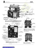
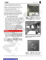
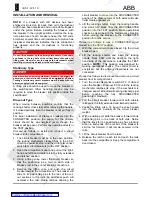
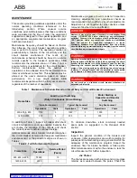
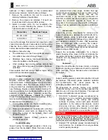
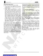
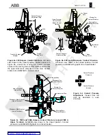
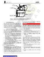
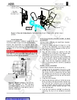
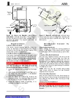
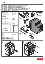
See the illustrations of Figure 1 for feature location.
Note that not all features are found on a particular
breaker depending on the type designation.
Anti-pump Lockout Relay (EO)
(Not illustrated - internal feature)
The lockout relay functions within the control relay
device. The relay prevents subsequent circuit breaker
closure until the previous close signal is first released
and then reapplied. Anti-pump circuitry prevents
repeated open-close cycling during a trip-free
condition or reclosing onto an automatic trip event.
Automatic Spring Discharge (EO)
(Not illustrated – internal feature)
Electrically operated draw-out breakers are designed
to discharge the closing springs when a breaker is
racked into the DISCONNECTED position. This
internal feature prevents inadvertent breaker closure
while handling the breaker outside of the enclosure.
The spring discharge occurs just before reaching the
DISCONNECTED position. The springs will not store
a new charge until the breaker is moved out of the
DISCONNECTED position.
Note:
In early model draw-out breakers [prior 1970],
the closing springs are automatically discharged when
the breaker is pulled to the fully withdrawn position. A
ramp on the cubicle floor drives the close latch
release rod (on the control relay device) as the
breaker is withdrawn from the switchgear.
Automatic Trip Indicator
This is a white indicator marked “RESET”. It is
spring-loaded in the latched position, popping out
upon automatic tripping. The device only indicates
tripping during an automatic event. The cause for
indication should be investigated before resetting the
trip indicator and subsequently re-closing the circuit
breaker. Reset the indicator by physically pushing it
back into its normally latched position. This feature
may be coordinated with a lockout feature.
Automatic Trip Alarm Contacts (Optional)
A microswitch coordinated with the automatic trip
indicator provides remote indication of an automatic
trip event. The trip indicator actuates a roller on the
alarm switch during an overcurrent trip. Resetting the
automatic trip indicator also resets the alarm contacts.
Automatic Trip Lockout (Optional)
Following a fault, the lockout places the circuit breaker
trip-free by holding the tripper bar paddle in the trip
position. The circuit breaker cannot be closed until the
indicator is manually reset on the breaker.
Close Button (EO)
The close push button electrically operates the close
coil (X) in the control relay device. The armature of
this coil actuates the close latch release rod. The rod
actuates the close latches, allowing the closing
springs to operate the breaker mechanism. When no
control power exists, the manual close lever must be
used to close the circuit breaker.
Close Handle (MO)
(Not illustrated)
The T-shaped handle both charges the closing springs
and closes the contacts of a MO circuit breaker in one
sequence. The closing speed is independent of the
handle action. The closing handle also performs the
slow-close operation used for simultaneous contact
adjustment (see
Slow-close Procedure
).
Close Lever (EO)
The close lever manually closes an EO breaker by
mechanically actuating the close latches. MO breakers
do not have this lever since the mechanism charges
and closes in one operation.
Contact Position Indicator
This mechanical flag indicates the status of the
breaker contacts as either “OPEN” or “CLOSED.”
Lifting Yoke (Optional)
Use a lifting yoke to safely install a breaker into
switchgear. The yoke hooks into the vertical frame
channels as shown in Figure 1a. The bolted
construction allows the yoke to be used for both small
and large frame breakers. If a yoke is unavailable, use
chain hooks in the upper hole of the vertical frame
channels.
Locking Hasp
All K-Line circuit breakers are equipped with a
provision for padlocking the mechanism in an open,
trip-free condition in any of the draw-out positions. The
hasp accepts one or more padlocks. When locked, the
trip-free condition results from the engagement of the
manual trip button linkage.
To lock the breaker open:
1. Trip the breaker open.
2. Depress and hold the mechanical trip button, then
pull the locking hasp outward.
3. Insert
lock(s).
When locked, a breaker can neither be racked
between positions nor closed. For EO breakers,

