ABB IRP Скачать руководство пользователя страница 8

41-133S

8

Directional Overcurrent Ground Relays

Types IRP, IRC and IRD

b.

The contact gap adjustment for the overcurrent

unit is made with the moving contact in the reset
position i.e., against the right side of the bridge.
Move in the left-hand stationary contact until it
just touches the moving contact then back off the
stationary contact 2/3 of one turn for a gap of
approximately .020”. The clamp holding the sta-
tionary contact housing need not be loosened for
the adjustment since the clamp utilizes a
spring-type action in holding the stationary con-
tact in position.

c.

The sensitivity adjustment is made by varying

the tension of the spiral spring attached to the
moving element assembly. The spring is
adjusted by placing a screwdriver or similar tool
into one of the notches located on the periphery
of the of the spring adjuster and rotating it. The
spring adjuster is located on the underside of the
bridge and is held in place by a spring type
clamp that does not have to be loosened prior to
making the necessary adjustments.

Before applying current, block open the nor-
mally-closed contact of the directional unit insert
the tap screw in the minimum value tap setting
and adjust the spring such that the contacts will
close as indicated by a neon lamp in the contact
circuit when energized with the required current.
The pick up of the overcurrent unit with the tap
screw in any other tap should be within 5% of tap
value.

If adjustment of pick-up current in-between tap
settings is desired insert the tap screw in the next
lowest tap setting and adjust the spring as
described. It should be noted that this adjustment
results in a slightly different time characteristic
curve and burden.

7.4.1 Directional Unit (D) 

In the type IRP and IRC relays the directional unit is
the lower cylinder unit. In the type IRD the directional
units are the lower and middle cylinder units.

a.

The upper bearing screw should be screwed

down until there is approximately .025 clearance
between it and the top of the shaft bearing. The
upper pin bearing should then be securely
locked in position with the lock nut.

b.

Contact gap adjustment for the directional unit is

made with the moving contact in the reset posi-
tion, i.e., against the right side of the bridge.

Advance the right hand stationary contact until
the contacts just close. Then advance the sta-
tionary contact an additional one-half turn.

Now move in the left-hand stationary contact
until it just touches the moving contact. Then
back off the stationary contact 3/4 of one turn for
a contact gap of .020” to .024”. The clamp hold-
ing the stationary contact housing need not be
loosened for the adjustment since the clamp uti-
lizes a spring-type action in holding the station-
ary contact in position.

c.

Insert tap screw of overcurrent unit in highest

tap. The sensitivity adjustment is made by vary-
ing the tension of the spiral attached to the mov-
ing element assembly. The spring is adjusted by
placing a screwdriver or similar tool into one of
the notches located on the periphery of the
spring adjuster and rotating it. The spring
adjuster is located on the underside of the bridge
and is held in place by a spring type clamp that
does not have to be loosened prior to making the
necessary adjustments. Set red mark on core to
left side of cylinder unit and adjust spring to just
reset.

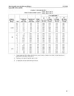
The spring is to be adjusted such that the con-
tacts will close as indicated by a neon lamp in the
contact circuit when energized with the required
current and voltage as shown in Table 1 (page
10)
. This table indicates that the spring can be
adjusted when the phase angle relationship
between the operating circuit and the polarizing
circuit is at the maximum torque angle or when
the circuit relationship has the operating and
polarizing circuits in phase.

d.

The magnetic plugs are used to reverse any

unwanted spurious torques that may be present
when the relay is energized on current or voltage
alone.

The reversing of the spurious torques is accom-
plished by using the adjusting plugs in the follow-
ing manner:

1.

Voltage circuit terminals on the voltage

polarized relays (IRP and IRD voltage polar-
ized unit) are short-circuited.

2.

The polarizing circuits of the current polar-

ized relays (IRC and IRD current polarized
unit) are open-circuited.

Содержание IRP

Страница 1: ...nsformer and two indicating con tactor switches ICS I and ICS T The principle component parts of the relays and their locations are shown in Figures 1 through 6 starting on page 19 2 1 TIME OVERCURRENT UNIT CO The electromagnets for the types IR 5 IR 6 IR 7 IR 8 and IR 9 relays have a main tapped coil located on the center leg of an E type laminated structure that produces a flux which divides and...

Страница 2: ...the core of the solenoid As the plunger travels upward the disc bridges the silver stationary contacts The TR 1 switch is a telephone relay A tapped resis tor is used to enable one to use the auxiliary switch on a 24 48 125 or 250 volt dc system connected per Figure 26 page 40 The operation of the CS 1 or TR 1 switch is controlled by the directional unit D which in turn directionally controls the ...

Страница 3: ...ws the instantaneous overcurrent unit closing time The voltage polarized curve B begins to deviate from curve A for less than 5 volts Both the directional unit and the overcurrent unit must operate before the trip circuit can be completed Hence the unit which takes the longer time to oper ate determines when the breaker will be tripped The overcurrent unit contacts cannot operate until the back co...

Страница 4: ...cuit breaker The indicating contactor switch has two taps that pro vide a pickup setting of 0 2 or 2 amperes To change taps requires connecting the lead located in front of the tap block to the desired setting by means of a screw connection 4 2 CONTACTS The moving contact assembly has been factory adjusted for low contact bounce performance and should not be changed The set screw in each stationar...

Страница 5: ...h which coordination is to be effected The connector screws on the tap plate above the time dial makes connections to various turns on the operating coil By placing this screw in the various tap plate holes the relay will just close its contacts at the corresponding current 4 5 6 7 8 10 12 amperes or as marked on the tap plate Since the tap block connector screw carries operating current be sure t...

Страница 6: ... then mechanically close in a direction opposite to that of the instanta neous unit contact Electrical characteristics and external connections to the relay would not be affected Field modifications can be made per the following procedures 1 Reverse the leads on the stationary contacts of the directional unit For the IRD reverse the leads on both directional units 2 Reverse the leads to switch jaw...

Страница 7: ...e operating time of the relay The operating times should equal those of Table 3 plus or minus 5 percent 7 1 4 Indicating Contactor Switches ICS I and ICS T a Close the contacts of the CO and pass sufficient dc current through the trip circuit to close the contact of ICS T This value of current should not be greater than the particular ICS T tap set ting being used The operation indicator target sh...

Страница 8: ...ng should then be securely locked in position with the lock nut b Contact gap adjustment for the directional unit is made with the moving contact in the reset posi tion i e against the right side of the bridge Advance the right hand stationary contact until the contacts just close Then advance the sta tionary contact an additional one half turn Now move in the left hand stationary contact until it...

Страница 9: ...nsion so that the moving contact will leave the backstop at tap value current 1 0 and will return to the backstop at tap value current 1 0 Time Curve Calibration Install the permanent magnet Apply the indicated current per Table 3 page 11 for permanent magnet adjustment e g IRP 8 2 times tap value and measure the operating time Adjust the permanent magnet keeper until the operating time correspond...

Страница 10: ...djustment Connect lead A to proper terminal per Figure 26 page 40 Block directional unit D contacts close and energize trip circuit with rated voltage Contacts of auxiliary switch CS 1 or TR 1 should make as indicated by a neon lamp in the contact circuit 8 0 RENEWAL PARTS Repair work can be done most satisfactorily at the factory However interchangeable parts can be fur nished to the customers wh...

Страница 11: ...wed out until Spurious Torque is in contact closing direction Then the plug is screwed in until Spurious Torque is reversed reversed Short circuit the voltage polarizing at the relay terminals before making the above adjustment TABLE 2 DIRECTIONAL UNIT CALIBRATION PERMANENT MAGNET ADJUSTMENT ELECTROMAGNET PLUGS TIME OVERCURRENT UNIT TYPE TIME DIAL POSITION CURRENT MULTIPLES OF TAP VALUE OPERATING ...

Страница 12: ... 30 36 32 30 28 26 24 49 43 38 35 33 29 51 45 40 38 34 30 28 21 16 15 12 11 31 24 20 18 16 15 24 13 8 5 6 0 4 6 2 9 9 0 5 0 3 0 2 1 1 5 0 93 6 5 3 3 2 1 1 4 1 1 0 7 2 4 1 2 0 7 0 6 0 37 0 24 0 43 0 27 0 20 0 15 0 11 0 08 0 40 0 25 0 18 0 14 0 10 0 07 46 37 34 32 31 28 36 32 29 27 26 24 48 42 37 35 33 29 51 45 40 38 34 31 28 21 17 15 13 12 31 24 20 18 16 15 Thermal capacities for short times other ...

Страница 13: ...106 0 121 2 14 2 240 0 272 0 11 5 182 0 216 0 26 0 420 0 472 0 IRC IRP IRD Degrees current lags voltages at tap value current Thermal capacities for short times other than one second may be calculated on the basis of time being inversely proportional to the square of the current φ ENERGY REQUIREMENTS 60 HERTZ DIRECTIONAL UNIT POLARIZING CIRCUIT BURDEN RELAY TYPE RATING VOLT AMPERES POWER FACTOR AN...

Страница 14: ...28 110 110 110 110 110 110 110 230 230 230 230 230 230 230 58 57 53 50 40 36 29 59 55 51 47 45 41 37 65 50 47 46 43 37 34 4 8 4 9 5 0 5 3 6 2 7 2 7 9 5 04 5 13 5 37 5 53 5 72 5 90 6 54 4 92 5 20 5 34 5 53 5 86 6 6 7 00 39 6 39 8 42 7 45 4 54 4 65 4 73 6 38 7 39 8 42 2 44 0 46 0 50 3 54 9 39 1 42 0 44 1 45 8 49 9 55 5 62 3 256 270 308 348 435 580 700 262 280 312 329 360 420 474 268 305 330 364 400 ...

Страница 15: ...67 66 62 60 58 67 66 64 63 62 59 57 65 63 61 59 56 53 47 3 92 3 96 3 96 4 07 4 19 4 30 4 37 3 88 3 90 3 93 4 09 4 12 4 20 4 38 4 00 4 15 4 32 4 35 4 40 4 60 4 92 20 6 20 7 21 0 21 4 23 2 24 9 26 2 21 0 21 6 22 1 23 1 23 5 24 8 26 5 22 4 23 7 25 3 26 4 27 8 30 1 35 6 103 106 114 122 147 168 180 110 118 126 136 144 162 183 126 143 162 183 204 247 288 270 288 325 360 462 548 630 308 342 381 417 448 5...

Страница 16: ...58 56 66 63 63 62 61 59 58 64 61 60 58 55 51 46 3 88 3 93 3 93 4 00 4 08 4 24 4 38 4 06 4 07 4 14 4 34 4 34 4 40 4 62 4 24 4 30 4 62 4 69 4 80 5 20 5 40 20 7 20 9 21 1 21 6 22 9 24 8 25 9 21 3 21 8 22 5 23 4 23 8 23 2 27 0 22 8 24 2 25 9 27 3 29 8 33 0 37 5 103 107 114 122 148 174 185 111 120 129 141 149 163 183 129 149 168 187 211 260 308 278 288 320 356 459 552 640 306 342 366 413 448 530 624 39...

Страница 17: ...69 67 62 57 53 70 66 64 62 60 58 56 68 63 60 57 54 48 45 2 38 2 38 2 40 2 42 2 51 2 65 2 74 2 38 2 40 2 42 2 48 2 53 2 64 2 75 2 38 2 46 2 54 2 62 2 73 3 00 3 46 21 0 21 0 21 1 21 2 22 0 23 5 24 8 21 0 21 1 21 5 22 0 22 7 24 0 25 2 21 3 21 8 22 6 23 6 24 8 27 8 31 4 132 134 142 150 170 200 228 136 142 149 157 164 180 198 146 158 172 190 207 248 292 350 365 400 440 530 675 800 360 395 430 470 500 5...

Страница 18: ...9 1 02 1 10 1 23 1 32 1 8 6 54 6 80 7 46 8 30 10 04 11 95 13 95 6 30 7 00 7 74 8 20 9 12 9 80 11 34 7 08 8 00 9 18 10 00 11 1 14 9 16 3 71 8 75 0 84 0 93 1 115 5 136 3 160 0 74 0 78 5 84 0 89 0 102 0 109 0 129 0 78 4 90 0 101 4 110 0 124 8 131 6 180 0 250 267 298 30 411 502 610 264 285 309 340 372 430 504 296 340 378 454 480 600 720 0 5 2 5 2 6 4 12 Range Factor Tap Value 3 Times 10 Times 20 Times...

Страница 19: ...t Unit and Saturating Transformer 2 Current Polarized Directional Unit 3 Voltage Polarized Directional Unit 4 Time Overcurrent Unit 5 Indicating Contactor Switches 6 Auxiliary Switch Figure 2 Type IRD Relay without Case Rear View 1 Varistor 2 Saturating Transformer 3 E type Electromagnet Sub 1 9664A15 Photo Sub 1 9664A16 Photo 6 1 2 3 4 5 1 2 3 ...

Страница 20: ...oto 1 Stationary Contacts 2 Stationary Contact Pressure Spring 3 Magnetic Adjusting Plugs 4 Upper Bearing Screw 5 Moving Contact 6 Spring Adjuster Clamp 7 Current Bias Vane Photo 1 Tap Block 2 Time Dial 3 Control Spring Assembly 4 Disc 5 Stationary Contact Assembly 6 Magnetic Plugs 7 Permanent Magnet 4 7 2 1 1 5 3 6 1 6 2 5 3 4 7 ...

Страница 21: ...d Relays Types IRP IRC and IRD Figure 5 Instantaneous Overcurrent Unit Figure 6 Indicating contactor Switch ICS 1 Instantaneous Overcurrent Unit 2 Stationary Contact 3 Moving Contact 4 Saturating Transformer 5 Tap Block Photo Photo 2 3 1 5 4 ...

Страница 22: ...41 133S 22 Directional Overcurrent Ground Relays Types IRP IRC and IRD Figure 7 internal Schematic of the Type IRP Relay in the Type FT 31 Case Sub 9 184A033 Denotes change since previous issue ...

Страница 23: ...41 133S 23 Directional Overcurrent Ground Relays Types IRP IRC and IRD Figure 8 Internal Schematic of the Type IRC Relay in the Type FT 31 Case Sub 8 184A034 Denotes change since previous issue ...

Страница 24: ...41 133S 24 Directional Overcurrent Ground Relays Types IRP IRC and IRD Figure 9 Internal Schematic of the Type IRD Relay in the Type FT 41 Case Sub 11 184A020 Denotes change since previous issue ...

Страница 25: ...tional Overcurrent Ground Relays Types IRP IRC and IRD Sub 2 9654A57 Figure 10 Internal Schematic of the Type IRP Relay with Field Modified Reversed D Contacts in the Type FT 31 Case Denotes change since previous issue ...

Страница 26: ...tional Overcurrent Ground Relays Types IRP IRC and IRD Figure 11 Internal Schematic of the Type IRC Relay with Field Modified Reversed D Contacts in the Type FT 31 Case Denotes change since previous issue Sub 2 9654A58 ...

Страница 27: ...tional Overcurrent Ground Relays Types IRP IRC and IRD Sub 2 9654A56 Figure 12 Internal Schematic of the Type IRD Relay with Field Modified Reversed D Contacts in the Type FT 41 Case Denotes change since previous issue ...

Страница 28: ...41 133S 28 Directional Overcurrent Ground Relays Types IRP IRC and IRD Sub 5 289B506 Figure 13 External Schematic of the IRP Relay for Ground Fault Protection ...

Страница 29: ...41 133S 29 Directional Overcurrent Ground Relays Types IRP IRC and IRD Figure 14 External Schematic of the IRC Relay for Ground Fault Protection Sub 4 289B507 ...

Страница 30: ...41 133S 30 Directional Overcurrent Ground Relays Types IRP IRC and IRD Figure 15 External Schematic of the IRD Relay for Ground Fault Protection Sub 4 289B508 ...

Страница 31: ... 133S 31 Directional Overcurrent Ground Relays Types IRP IRC and IRD Sub 1 619584 Figure 16 Typical Time Curves of the Time Overcurrent Unit of the Short Time 2 Relays Denotes change since previous issue ...

Страница 32: ...41 133S 32 Directional Overcurrent Ground Relays Types IRP IRC and IRD Sub 2 418245 Figure 17 Typical Time Curves of the Time Overcurrent Unit of the Long Time 5 Relays ...

Страница 33: ...133S 33 Directional Overcurrent Ground Relays Types IRP IRC and IRD Figure 18 Typical Time Curve of the Time Overcurrent Unit of the Definite Time 6 Relays Sub 3 418246 Denotes change since previous issue ...

Страница 34: ...133S 34 Directional Overcurrent Ground Relays Types IRP IRC and IRD Sub 3 418247 Figure 19 Typical Time Curve of the Time Overcurrent Unit of the Definite Time 7 Relays Denotes change since previous issue ...

Страница 35: ...41 133S 35 Directional Overcurrent Ground Relays Types IRP IRC and IRD Sub 3 418248 Figure 20 Typical Time Curve of the Time Overcurrent Unit of the Definite Time 8 Relays ...

Страница 36: ...41 133S 36 Directional Overcurrent Ground Relays Types IRP IRC and IRD Sub 2 418249 Figure 21 Typical Time Curve of the Time Overcurrent Unit of the Definite Time 9 Relays ...

Страница 37: ...41 133S 37 Directional Overcurrent Ground Relays Types IRP IRC and IRD Sub 2 288B655 Figure 22 Typical Time Curve of the Time Overcurrent Unit of the Definite Time 11 Relays ...

Страница 38: ...ent Ground Relays Types IRP IRC and IRD Sub 2 538109 Figure 23 Typical Operating Times For The Directional Unit Figure 24 Typical Operating Times For the Instantaneous Overcurrent Unit Denotes change since previous issue Sub 7 538108 ...

Страница 39: ...41 133S 39 Directional Overcurrent Ground Relays Types IRP IRC and IRD Sub 5 184A118 Figure 25 Diagram Of Test Connections Of The Time Overcurrent Unit ...

Страница 40: ...41 133S 40 Directional Overcurrent Ground Relays Types IRP IRC and IRD Figure 26 Selection of Proper Voltage Tap for Auxiliary Switch Operation Sub 4 184A316 Sub 1 1518B95 Figure 27 Test Connections ...

Страница 41: ...41 133S 41 Directional Overcurrent Ground Relays Types IRP IRC and IRD NOTES ...

Страница 42: ...41 133S 42 Directional Overcurrent Ground Relays Types IRP IRC and IRD NOTES ...

Страница 43: ...41 133S 43 Directional Overcurrent Ground Relays Types IRP IRC and IRD Figure 28 Outline and Drilling Plan for the IRP and IRC in the Type FT 31 Case Sub 17 57D7902 Sub 17 57D7902 ...

Страница 44: ...e Drive Coral Springs Florida 33065 TEL 954 752 6700 FAX 954 345 5329 Directional Overcurrent Ground Relays Types IRP IRC and IRD visit our website at www abbus com papd Sub 18 57D7904 Figure 29 Outline and Drilling Plan for the IRD Relay i n the Type FT41 Case ...

Отзывы: