


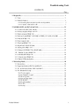


Troubleshooting Tools
Product Manual
3
Troubleshooting Tools
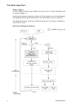
Generally speaking, troubleshooting should be carried out as follows:
• Read any error messages shown on the teach pendant display.
What these messages mean is described in System and Error Messages.
• Check the LEDs on the units. See Indication LEDs on the Various Units page 14.
• Switch the power off and then on. When the robot is started up, a self diagnostic is
run which detects any errors. The tests performed during the self diagnostic are
described in the chapter Diagnostics page 3.
• Check the cables, etc., with the help of the circuit diagram.
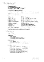
1 Diagnostics
The control system is supplied with diagnostic software to facilitate troubleshooting
and to reduce downtime. Any errors detected by the diagnostics are displayed in plain
language with an code number on the display of the teach pendant.
All system and error messages are logged in a common log which contains the last 50
messages saved. This enables an “error audit trail” to be made which can be analysed.
The log can be accessed from the Service window using the teach pendant during nor-
mal operation and can be used to read or delete the logs. All system and error messages
available are listed in User’s Guide.
The diagnostic programs are stored in flash PROM on the robot computer board. The diag-
nostic programs are executed by the I/O computer.
The control system runs through various tests depending on the start up mode:
Cold Start -
Cold starts occur normally only when the control system is started the first time, or when
any computer board has been replaced, or when the batteries have been disconnected.
First, the test programs are executed by the robot computer (I/O computer) and the
main computer. These tests and the test results are displayed on the teach pendant. If
the tests do not indicate any errors, a message will appear on the display, requesting
you to insert a system diskette into the disk drive. If, however, the diagnostics detect
an error, a message will appear on the display and the test will be stopped until the user
hits a key on the teach pendant or on a terminal connected to the front connector on the
robot computer.
Warm Start -
is the normal type of start up when the robot is powered on. During a warm start, only a
subset of the test program is executed. These tests and the test results are displayed on the
teach pendant.
Another type of warm start, INIT, is carried out via a push button located on the back-
plane (see section 3). INIT is very similar to switching the power on. The tests that are
run depend on whether or not the system is booted.
Содержание IRB 6400R
Страница 4: ...Description 20 Product Specification IRB 1400 M97A BaseWare OS 3 0 ...
Страница 6: ...Introduction 2 Product Manual ...
Страница 10: ...Introduction 6 Product Manual ...
Страница 12: ...Product Specification IRB 6400R 2 Product Specification IRB 6400R M99 BaseWare OS 3 2 ...
Страница 78: ...Accessories 68 Product Specification IRB 6400R M99 BaseWare OS 3 2 ...
Страница 80: ...Product Specification RobotWare 2 Product Specification RobotWare for BaseWare OS 3 2 ...
Страница 82: ...Introduction 4 Product Specification RobotWare for BaseWare OS 3 2 ...
Страница 104: ...Interbus S 3 2 26 Product Specification RobotWare for BaseWare OS 3 2 ...
Страница 110: ...I O Plus 3 2 32 Product Specification RobotWare for BaseWare OS 3 2 ...
Страница 128: ...PalletWare 50 Product Specification RobotWare for BaseWare OS 3 2 ...
Страница 132: ...Safety 2 Product Manual ...
Страница 148: ...System Description CONTENTS Page 2 Product Manual ...
Страница 158: ...Structure System Description 12 Product Manual ...
Страница 160: ...Computer System System Description 14 Product Manual ...
Страница 164: ...I O System System Description 18 Product Manual ...
Страница 168: ...Safety System System Description 22 Product Manual ...
Страница 170: ...External Axes System Description 24 Product Manual ...
Страница 174: ...Installation and Commissioning CONTENTS Page 4 Product Manual IRB 6400R ...
Страница 193: ...Installation and Commissioning On Site Installation Product Manual IRB 6400R 23 Figure 17 Cutting the cam Remove 90 30 ...
Страница 196: ...On Site Installation Installation and Commissioning 26 Product Manual IRB 6400R ...
Страница 270: ...Installing the Control Program Installation and Commissioning 100 Product Manual IRB 6400R ...
Страница 292: ...Maintenance CONTENTS Page 2 Product Manual IRB 6400R ...
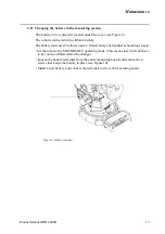
Страница 299: ...Maintenance Product Manual IRB 6400R 9 Figure 4 Lubricating gearbox axis 1 4 3 1 2 ...
Страница 312: ...Troubleshooting Tools CONTENTS Page 2 Product Manual ...
Страница 350: ...Troubleshooting Tools 40 Product Manual ...
Страница 352: ...Fault tracing guide 2 Product Manual ...
Страница 362: ...Fault tracing guide 12 Product Manual ...
Страница 375: ...Motor units Repairs 12 Product Manual IRB 6400R ...
Страница 401: ...Arm System Repairs 38 Product Manual IRB 6400R ...
Страница 409: ...Cabling Repairs 46 Product Manual IRB 6400R ...
Страница 441: ...Special Tools List Repairs 80 Product Manual IRB 6400R ...
Страница 479: ...Part List and Spare Parts Product Manual IRB 6400R 38 ...
Страница 480: ...Part List and Spare Parts Product Manual IRB 6400R 39 ...
Страница 481: ...Part List and Spare Parts Product Manual IRB 6400R 40 ...


