


IM300 Intelligent Power Monitoring Instrument
4
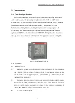
F
ig 2.1.1. Device size fig. (Unit: mm)
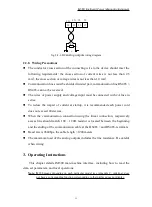
2.1.2. Installation
The IM300 should be mounted on the switch gear panel.
Panel opening dimensions shown in fig. 2-1-2-1:
Fig 2.1.2.1 Slots on the panel (unit: mm)
Fig 2.1.2.2 Card is removed
Taking into account the length of wire, the rear panel must be 100mm depth for
accommodating IM300. Actual installation, it normally takes the rear there is
some space (at least 130 × 130 × 100mm), ease of installation and wiring.
Take off the installation card on both sides of the device., as shown in fig. 2.1.2.2,
with the thumb and forefinger of one hand the fixed head gently lift (lift force is
not too large, otherwise it may cause the fixed head fracture), the thumb of the
other hand in the direction of the arrow shown in FIG by pushing the catches can
be removed. When installing the device on the front panel push into the mounting
hole, then from the trench along the rear of the device will be installed on clip. As
shown in fig. 2.1.2.3, his hands were holding down the top and bottom sides of
the device, the top two in the thumb of the clip ends, even before the direction of
the arrow to push hard to make catches squeezing panel. After the installation of
two cards are installed, the device will be firmly fixed on the panel.
Содержание IM300 Series
Страница 1: ...IM300 Operational Manual ...
Страница 109: ...CNABB CNIIB IM300 201903 REV C ...


