ABB i-bus
®
KNX
Planning and application
FCC/S 1.X.X.1 | 2CDC 508 200 D0211 Rev A 359
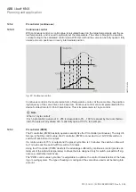
The device is controlled in accordance with the following schematic principle:
Fig. 62: 2CDC072055F0217
2CDC072055F0217
With three
Switch speed x
(x = 1, 2, or 3) group objects that are independent of each other, the fan
stages are controlled via the outputs of the Fan Coil Actuator.
Alternatively, fan control can be performed via the 1-byte group object
Switch fan speed
or via the
group object
Increase/decrease fan speed
.
Some fan control systems require an additional central switch-on mechanism (main switch) in addi-
tion to speed switching. Another output of the device may be used for this. The output must be
linked to the group object
Fan ON/OFF status
. This will switch on the main switch if at least one
fan speed is set. The main switch is also switched off when the fan is OFF (
Fan ON/OFF status=
0
).
12.2.1.1
Fan with changeover switch
Fans are usually controlled with a changeover switch.
The following control table results for a three-stage fan, which simulates the device with a group of
switch outputs:
Terminal C
Terminal D
Terminal E
OFF
0
0
0
Fan speed 1
1
0
0
Fan speed 2
0
1
0
Fan speed 3
0
0
1
Table 35: Terminal assignment


